Klingon D-7
← WIP Index
 This model is special to me because it is a model of firsts. It is the first
model I built with internal lighting. It is also the first model I painted
with an airbrush, rather than cheap rattlecans. Finally, it is the first
model I photographed with a real camera, bringing upon a hobby all of
its own.
This model is special to me because it is a model of firsts. It is the first
model I built with internal lighting. It is also the first model I painted
with an airbrush, rather than cheap rattlecans. Finally, it is the first
model I photographed with a real camera, bringing upon a hobby all of
its own.
In the process of firsts, many mistakes were made, much was learned, and
many future mistakes were avoided. The simple design of this kit was a
perfect beginner's project. I highly recommend TOS-era kits for people
wanting to start out building science fiction models.
This kit has since been superceded by Polar Lights' version, which is
more accurate than AMT's version in all the areas corrected in this build.
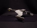
Photos of the completed build are available in the
Models Area.
1999-08-01
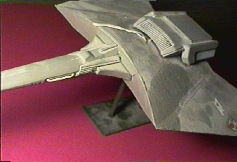
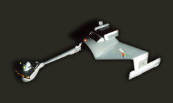
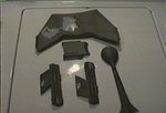
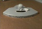
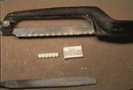
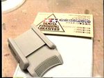
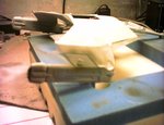
This model began its relationship with me having been previously
assembled. As can be seen from the dust, it was lying in a pile of junk in a
friend's basement for years. At first glance it looks like a well-built
model...
1999-08-01
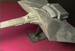
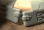
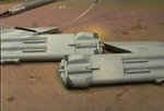
Upon closer inspection, the flaws in the handiwork come out. The model
was built by my friend when he was about ten years old. The pieces fit
decently, but the upper engine pod is incorrectly assembled. The hull has
very significant brush marks. The model was painted with thick acrylic hobby
paints.
1999-08-02
After soaking in warm water with detergent for a few hours, the paint was
quite willing to come off.
1999-08-02
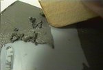
The paint was scraped off with a soft wooden paint stir stick. Areas that
were stubborn required a mild solvent; Methyl Hydrate (stove fuel) was used.
1999-08-02
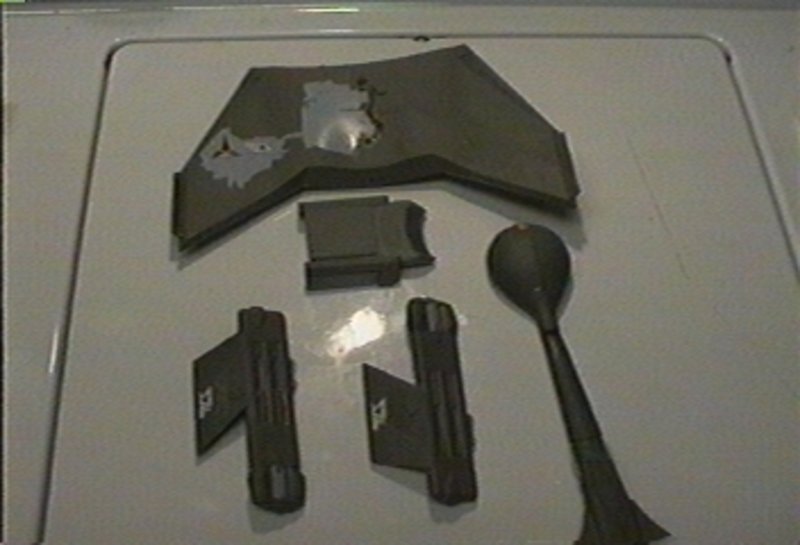
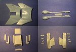
The parts were all cleaned and disassembled. Some of the upper engine
module parts did not take disassembly well, and may need to be replaced.
Decals were left on temporarily as they may have to be salvaged.
1999-08-06
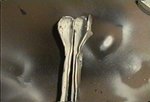
The window pattern molded into the boom's "head" was too far up.
Reference materials were consulted, and a more accurate pattern was applied.
The pattern is based on views of the original studio model, as well as Greg
Jein's newer version of this ship.
1999-08-06
Similarly, an accurate pattern for the bridge area windows was drawn on
with a Sharpie.
1999-08-06
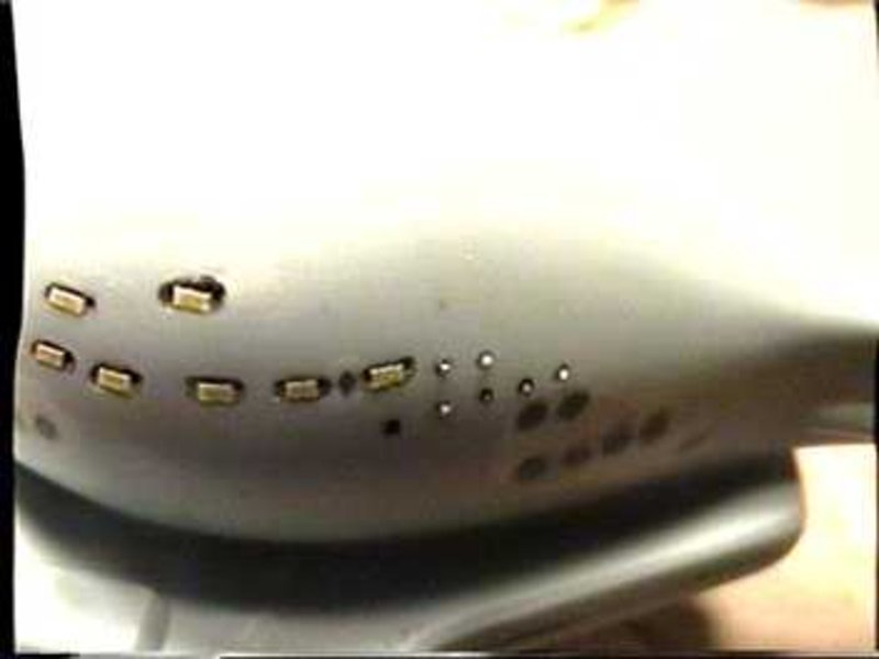
The windows in the "head" and along the boom were cut out so that the
model can be lit. The round windows will be lit with 0.030" fiber optic
strands. A #68 drill bit was used for their holes. The original window holes
were filled with Squadron Putty.
1999-08-29
A test with the clear resin that will be used to fill the windows
revealed that if the windows of the bridge area were cut to their final
size, it would be very hard to fill them with the thick resin. Instead, the
windows were cut in groups. This will make filling easier, and light should
diffuse more evenly. The original shape will be restored at the painting
stage, when the proper window shapes are masked.

1999-09-01
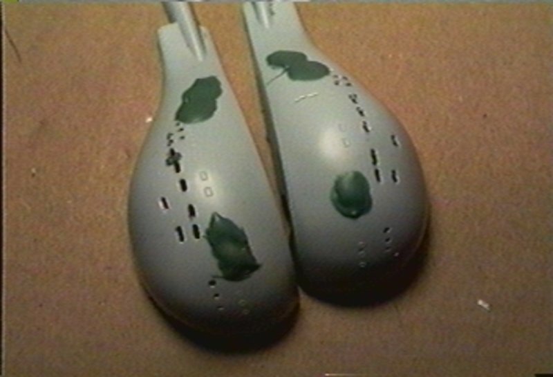
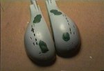
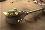
One of the inaccuracies of this model are the clear green vents on either
side of the bridge module. One has to wonder how those came to be. The
correct pattern is a row of concave half-pipes.
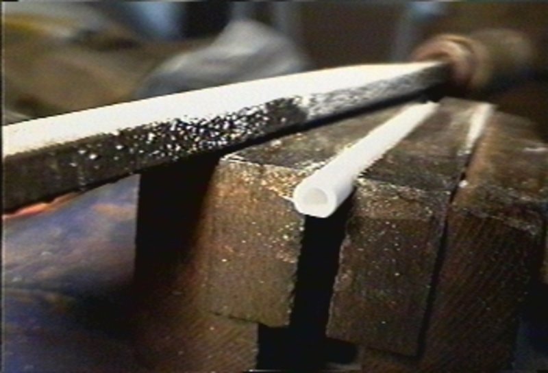
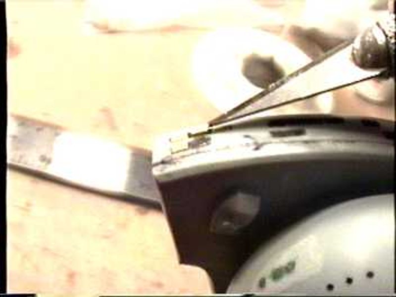
Replicating the proper pattern started with 5/32" polystyrene tube. A
length was clamped down, and two opposite sides were sanded to a flat edge.
1999-09-01
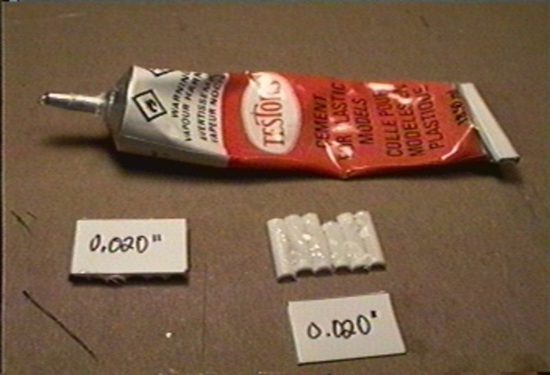
The tube was cut lengthwise through the flattened tube walls. The tube
was split into twelve pieces, which were then lined up and glued in two
groups of six. The flattened walls leave no space between each piece of
tube. The groups were backed with 0.020" sheet styrene for added strength.
1999-09-01
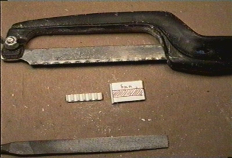
A 5mm-wide strip was cut from each of the groups. The surfaces of the
parts were sanded flat.
1999-09-01
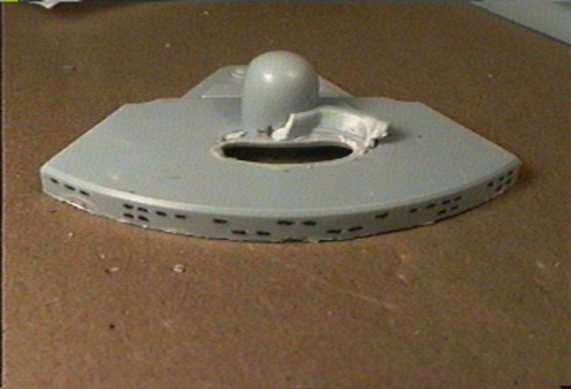
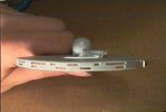
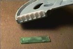
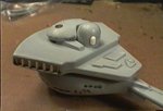
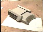
The replacement vents were installed into the bridge module part. Here is
the result alongside the original kit part.
1999-09-01
The next step involved lightproofing the kit. A coat of black paint was
spray painted into every part that will contain lights. This layer will
prevent light leaking through the plastic. The black was covered with a coat
of white that will help distribute light evenly in the model.
1999-09-03
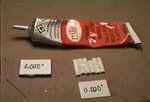
The long windows of the "head" and boom were filled with clear polyester
resin. This resin is not recommended for its strong odour and short working
time. Nonetheless, it was the only available clear plastic.
0.030" fiber optic strands cut to lengths of approximately 12mm were
placed in the round window holes and glued in place. A bit was left
protruding on the outside of the hull so that it is not buried in paint.
They should catch light from the LEDs that will light this area.

1999-09-04
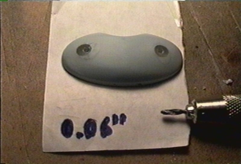
Much like the vents on the side of the bridge, the lights at the top of
the bridge were not accurately designed. The oversized holes were filled
with resin. A 0.060" drill bit was used to cut holes that will accept lights
of the proper size.

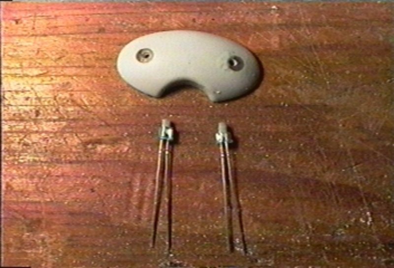
1999-09-04
Green LEDs of 0.060" diameters are hard to come by. Instead, custom LEDs
were turned down from 3mm green LEDs in a drill chuck turning along a file.
1999-09-04
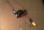
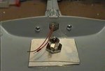
The new LEDs were glued into place and joined in series along with a
resistor appropriate for them to operate at 12V.

1999-09-04
The windows in the bridge module were now filled with the clear resin.
Scotch tape applied tightly to the exterior of the part acted as a
containing form while the resin was applied from the back.
1999-09-04
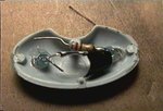
White LEDs are still too expensive. The model will be lit with yellow
LEDs instead. Because the LEDs will be facing directly out the windows,
dimmer LEDs are preferable. For even light, there are many of them.

1999-09-04
The bridge module LEDs were glued in place. The texture of the white
paint is due to the white paint being incompatible with the black paint. It
should not be a very serious problem.

1999-09-10
The bridge has been glued in place.
1999-09-10
The bridge module was glued shut with super glue. The two pairs of wires
are for the position lights and the interior lighting.

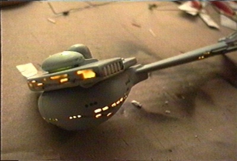
1999-09-10
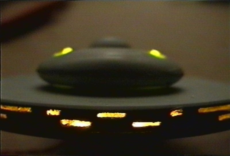
A light test confirms everything still works after the part was
assembled.

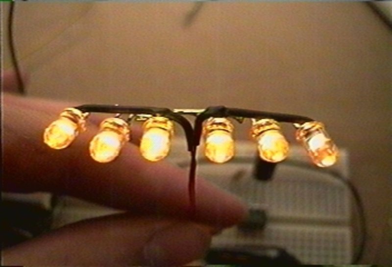
1999-09-25
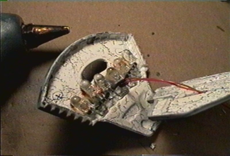
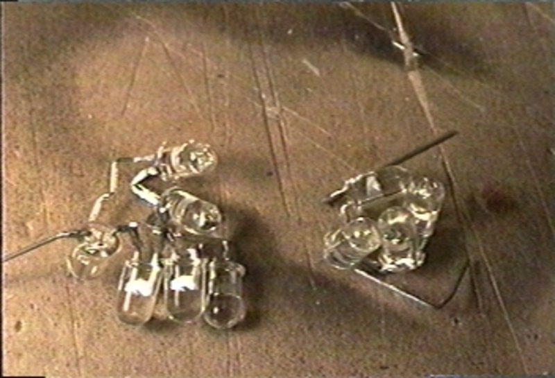
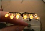
The "head" will be lit with ten yellow LEDs. They were arranged to point
at optimal positions inside the hull. Each LED is designed to run at 2V, so
a chain of 6 makes up the 12V supplied. The 4-LED group will be paired with
two LEDs that light the windows on the boom.
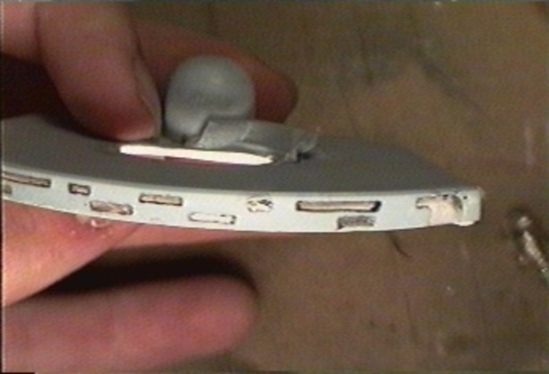
1999-09-25
This shows how the group of LEDs fits the part, pointing at the windows,
while leaving enough room for the torpedo launcher part.

1999-09-25
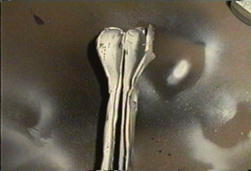
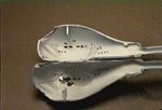
The boom windows will be lit with a pair of LEDs pointing at each other.
To make the light go out the sides so as to illuminate the windows, the
curved lenses of the LEDs were filed to a 45° angle.

1999-09-25
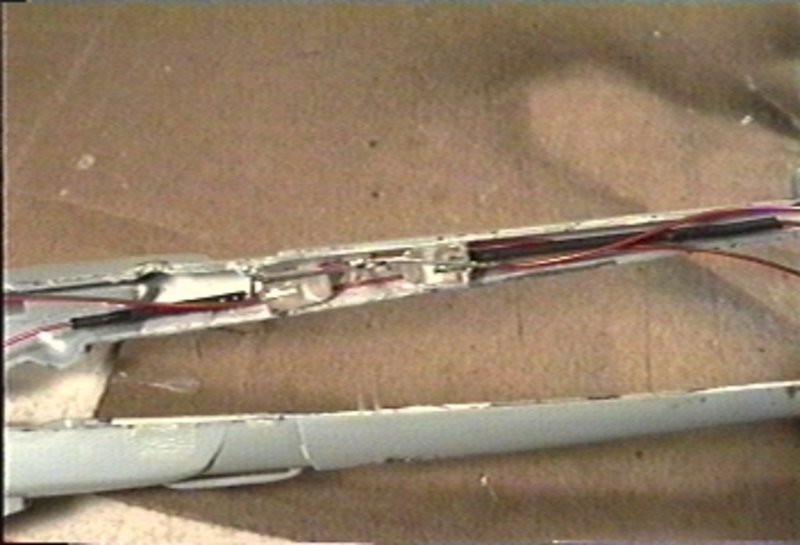
All of the electronics in the forward part of the ship were wired up. The
bridge module was glued to one of the halves of the boom.

1999-09-25
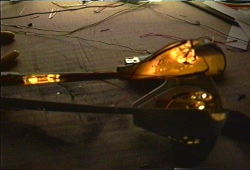
A final light test ensures that everything works as designed.
1999-09-25
The halves of the boom were glued together with super glue. There are now
only two wires sticking out of the back of this entire unit, which contains
eighteen LEDs.
2000-02-26
Greg Jein's version of this ship, as seen in the Deep Space Nine episode
"Trials and Tribble-ations," had a strobe in the upper hull, just behind
where the boom was attached. A yellow 3mm LED was turned down to fit a
0.060" hole. It was attached to a strobe circuit built around a simple 555
timer chip.
2000-07-08
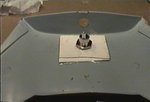
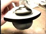
A missing detail on the back of the bridge dome was created from a piece
of sprue.

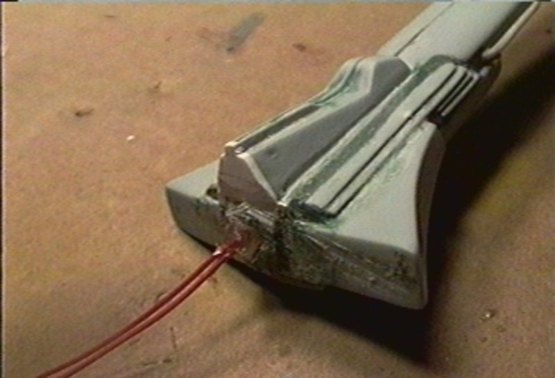
2000-07-08
The vents on either side of the boom were glued in place, and the giant
gap around them was filled. Test fitting the boom to the rear hull also
resulted in a significant gap. A wedge was cut from 0.040" styrene sheet
that created a tighter fit.
2000-07-29
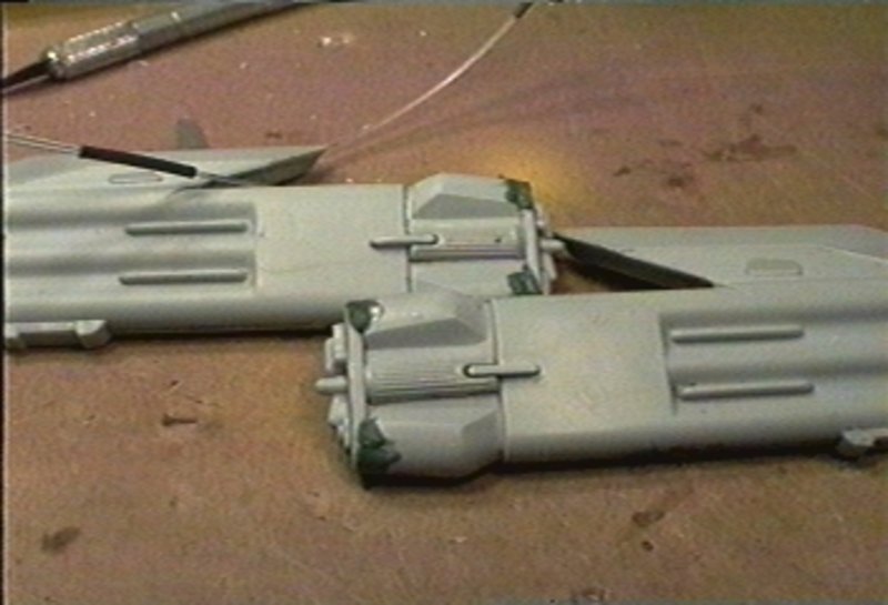
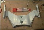
The front of each engine in Greg Jein's model contained two lights. Since
space in the nacelles is tight, all four lights will be powered from one LED
in main body of the ship. 0.030" optical fibers were installed to bring
light to the engines.
2000-07-29
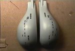
The rest of the nacelles were assembled and their gaps puttied.
2000-07-31
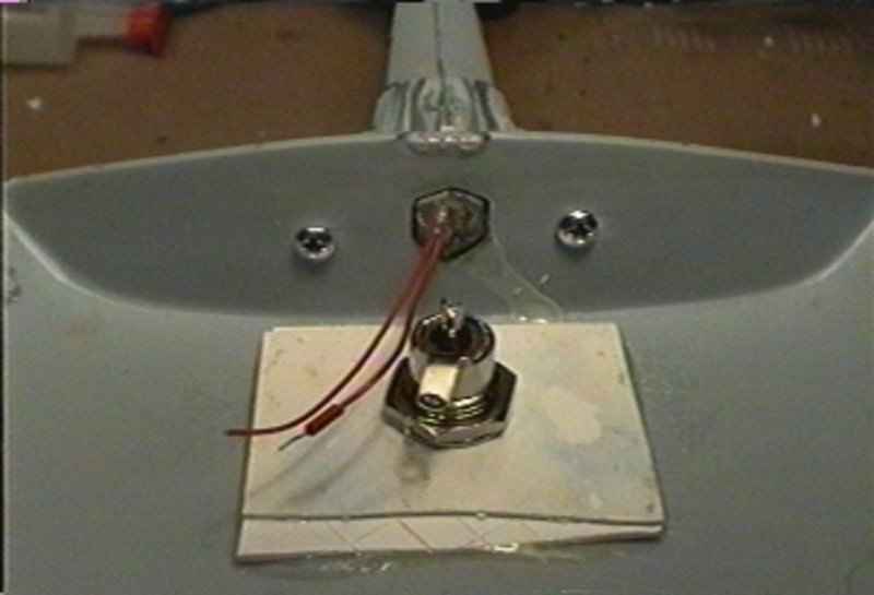
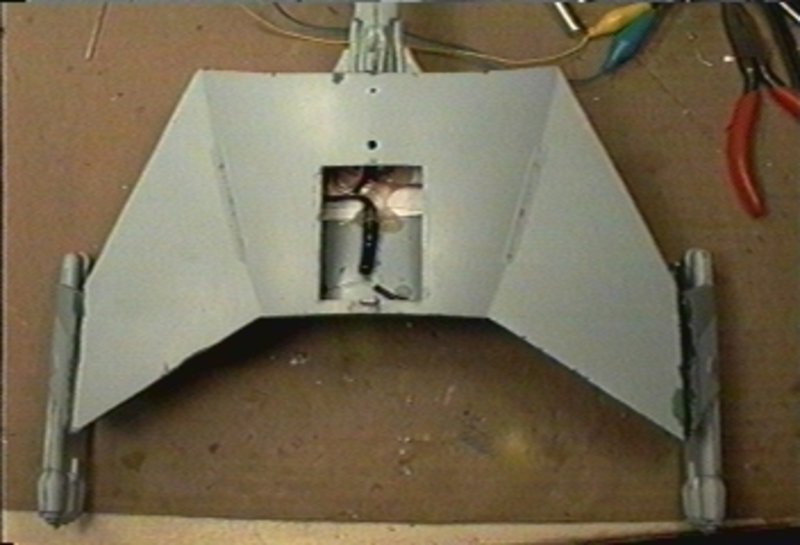
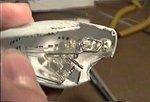
Power will be delivered to the model through a jack that will double as
the stand mounting point. Since it is expected to bear the weight of the
model, a heavy duty plug was installed and reinforced with extra sheet stock
epoxied in place.
2000-08-01
The previous mounting holes and the gap around the plug were filled with
Squadron Spot Putty. The engines were tacked in place with superglue, then
attached with epoxy for a sturdier bond.
2000-08-16
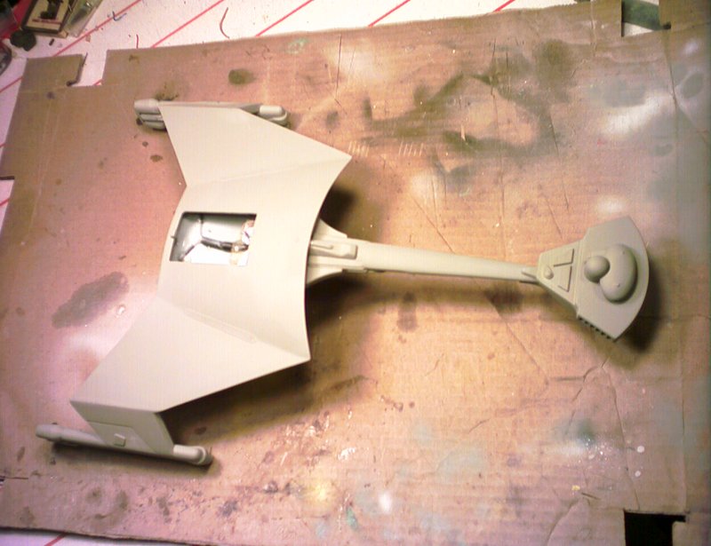
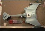
At this point, the major components of the ship were assembled. The boom
was glued in place with epoxy. The optical fibers from the engines are long
enough to reach the center of the rear hull.
2000-08-16
To ensure that boom does not snap off, it was further secured with two
screws.
2000-08-16
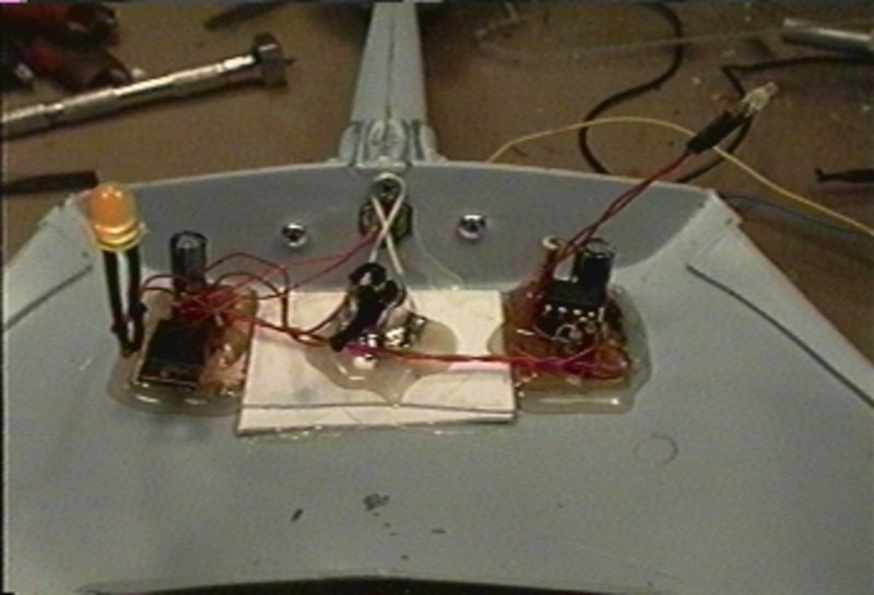
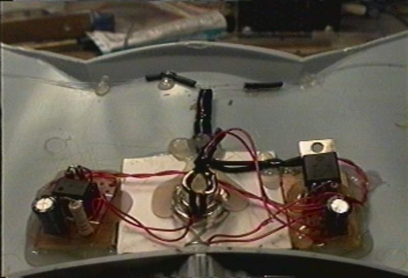
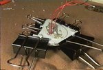
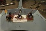
All of the electronic components were installed. A 12V regulator should
ensure clean power in the model. The strobing unit's LED awaits attachment
to the top hull piece. The LED that will light the nacelle lights also
awaits its fibers.
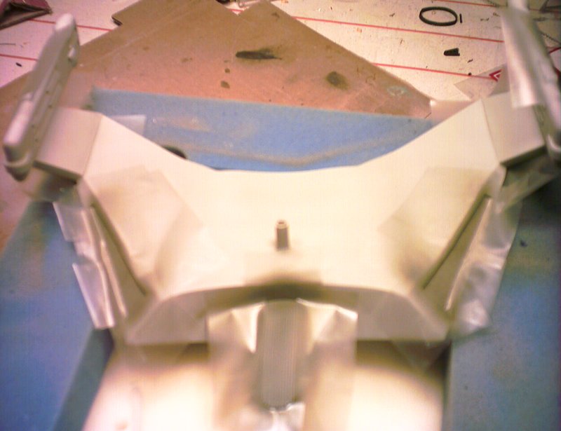
Preventing the boom from drooping over time is a major concern. A third
screw was added at the top of the boom junction. The head of this screw was
tied tightly with DC supply jack. The front wall of the rear hull no longer
flexes from the weight of the boom.
2000-08-16
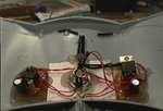
The fibers from the engines were attached to the front of their LED. A
piece of heatshrink tubing should prevent most light leaks while keeping
everything together.

2000-08-16
A 0.060" hole was drilled for the strobe LED in the top part of the hull.
Once installed, the part was glued down. The vents in the creases are not
accurate to either of the studio models, but were deemed to difficult to
remove.
The gaps all over the model are large, mostly as a result of the model
having been assembled twice. Putty was applied all over.
2001-05-13
The top module was assembled with a few replacement parts for ones that
broke during disassembly. The part was puttied, sanded, and prepared for
priming.
2001-05-13
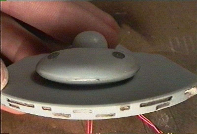
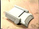
The part was primed with Testor's Acryl Primer. The base colour is
Testor's Light Sea Gray. Side vents were painted with Dunkelgrun. The front
vents were also lightly tinted with Dunkelgrun. The part was finished with
Testor's Dullcote. This piece was used as a test for the paint finish.
2001-05-16
The impulse engine module was the first part to be completed. It was set
aside.

2001-05-16
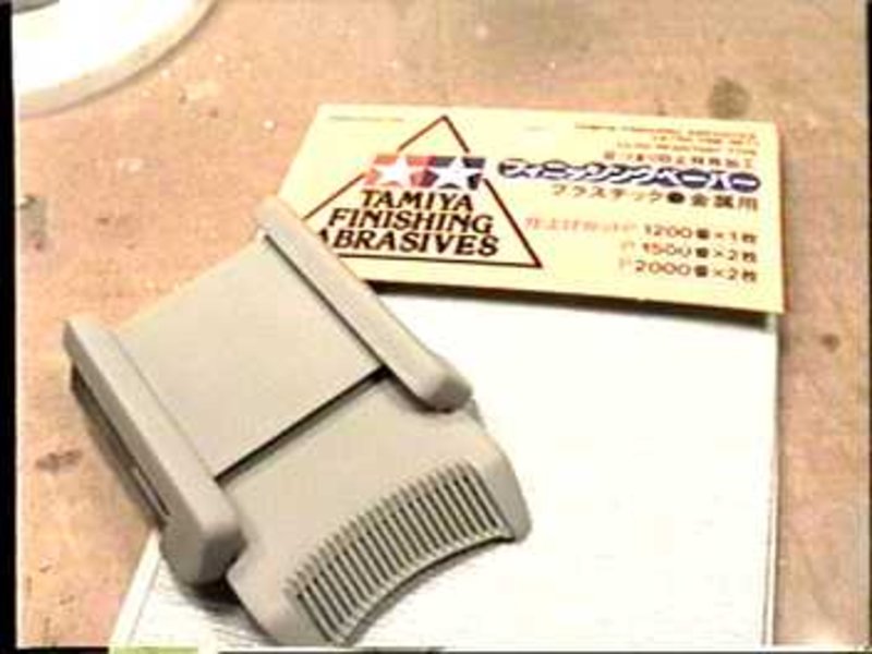
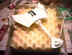
Masks for the long windows were cut from 1mm strips of Tamiya Masking
Tape. They were carefully put in place.

2001-05-18
The lower windows were treated to masks as well. For the round portholes,
several layers of white glue were dabbed into their ends. The glue dots
should act as circular masks.
2001-05-18
To prevent light leaks, all lit areas were given a thick coat of black
paint and the model was checked for any further bright spots.
2003-04-30
The first coat of primer was applied. Some areas needed more putty. The
puttying-sanding-priming process was repeated several times.

2003-04-30
Finally, the entire model was painted with Light Sea Gray.

2003-04-30
Frisket film masks were applied all around the hull. All of the details
were painted with various intensities of Dunkelgrun. This included the vent
under the boom, the vents on the sides of the boom, the vents on the front
of the wings, the vents on the sides of the wings, the details at the bottom
of the warp engines, and the vents behind the bridge.
2003-04-30
The vents in the warp pylons were given a light coat of Dunkelgrun. The
diamond shape plant-on was painted solid Dunkelgrun.

2003-04-30
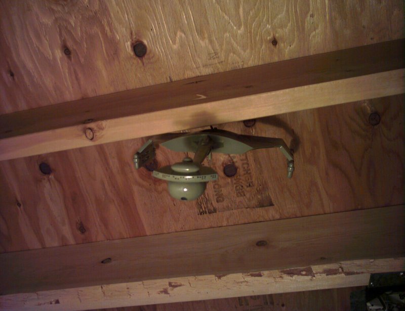
All of the masks were removed and their lines cleaned up. There was a
fair bit of clean-up work, since the masks had been in place for almost two
years. Prior to decaling, the model was given a few coats of Testor's Clear
Gloss. This will help with decal adhesion. The model was hung from the
ceiling to dry.

2003-04-30
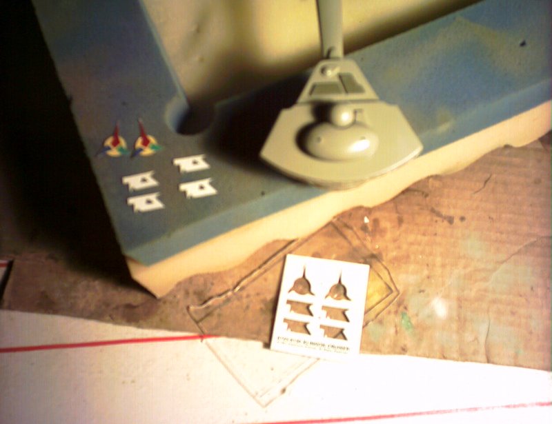
A fresh decal sheet was obtained from a friend who just happened to have
one. The decals were trimmed as close to the edge of the image as possible
and applied to the model. The model was sealed up with Testor's Dullcote.
The impulse engine module was glued with white glue, in case the electronics
ever need to be accessed.
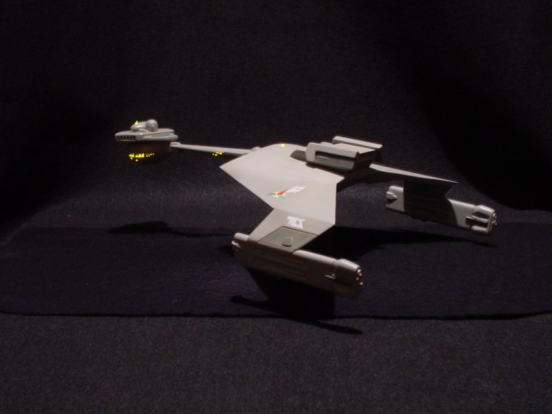
2003-05-13
This model was a good learning experience. Many useful techniques were
developed from dealing with all of the issues that came up. It was a great
model to experiment and learn on because of its simple assembly and paint
scheme.
copyright ©2007-2026 pat suwalski