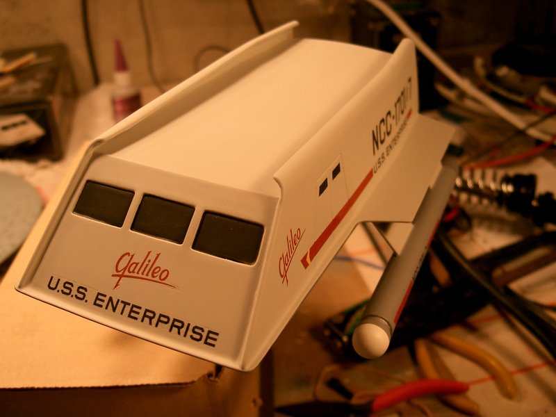
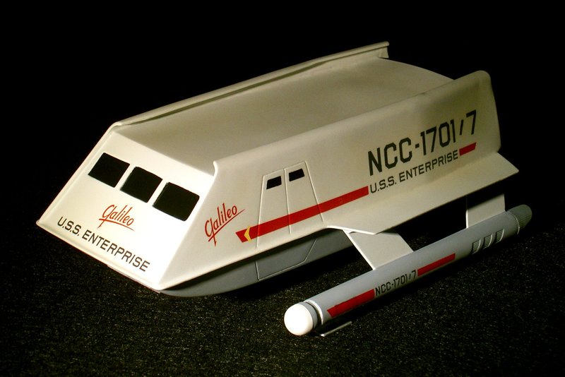
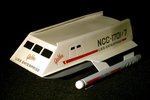
Shuttlecraft Galileo
← WIP Index
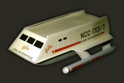 When I first opened the box for the Shuttlecraft Galileo model from AMT, I
was immediately shocked by how inaccurate the kit was. For such a simple
kit, the number of errors is astonishing. It is even more astonishing
considering that the contract for this model was awarded to AMT in exchange
for constructing the real filming miniature.
When I first opened the box for the Shuttlecraft Galileo model from AMT, I
was immediately shocked by how inaccurate the kit was. For such a simple
kit, the number of errors is astonishing. It is even more astonishing
considering that the contract for this model was awarded to AMT in exchange
for constructing the real filming miniature.
The model was initially going to be built using the techniques presented
in the November 1995 issue of FineScale Modeler, with a full interior and
exterior. The interior was eventually dropped for reasons explained below.
This model is my first build heavily modified from stock. The entire rear
section of te model was scratchbuilt.
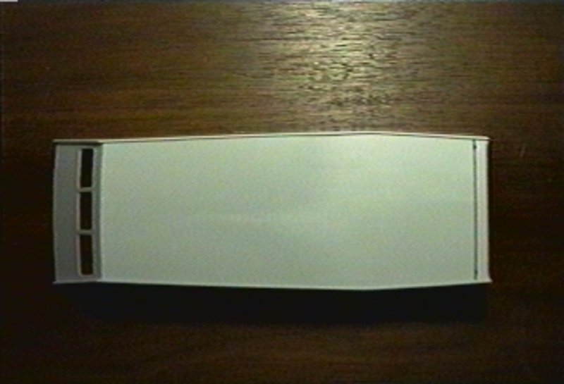
Photos of the completed build are available in the
Models Area.
1999-07-30
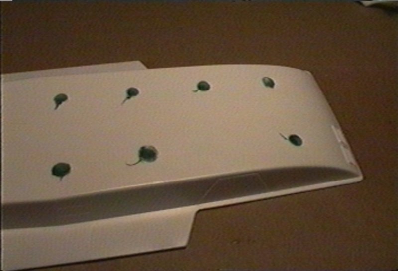
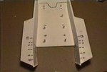
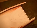
The first step was to flip the bottom half of the hull over and fill and
sand sinkholes corresponding to the positions of the seats inside the hull.
1999-07-31
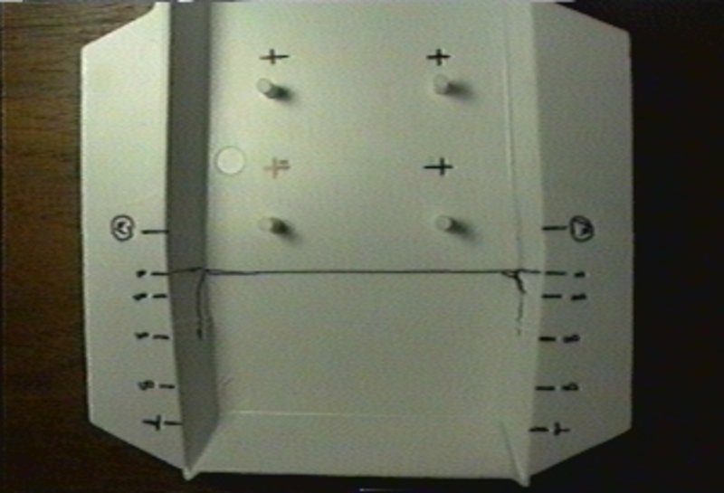
Using the plans Franz Joseph's "Starfleet Technical Manual" as reference,
the line marking where the impulse engine will be is marked. The entire back
wall of the model will need to be removed, and this line marks where the
roof will end, 5mm forward of the original back wall. On the studio model,
the side walls extended past where the roof ended.
1999-07-31
Similarly, the "Starfleet Technical Manual" was used to redraw the
positions of the front console and the seat positions. The console and first
row of seats went back 6mm. Each consecutive row of seats was spaced 25mm
from the row in front of it. This means that the position of the last row
moved up 14mm.

1999-07-31
Continuing with Franz Joseph's book, the position of the rear bulkhead
was marked with the circular marks. It was moved to 55mm from the back of
the shuttle, or 21mm forward of the original position.
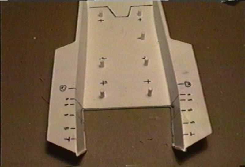
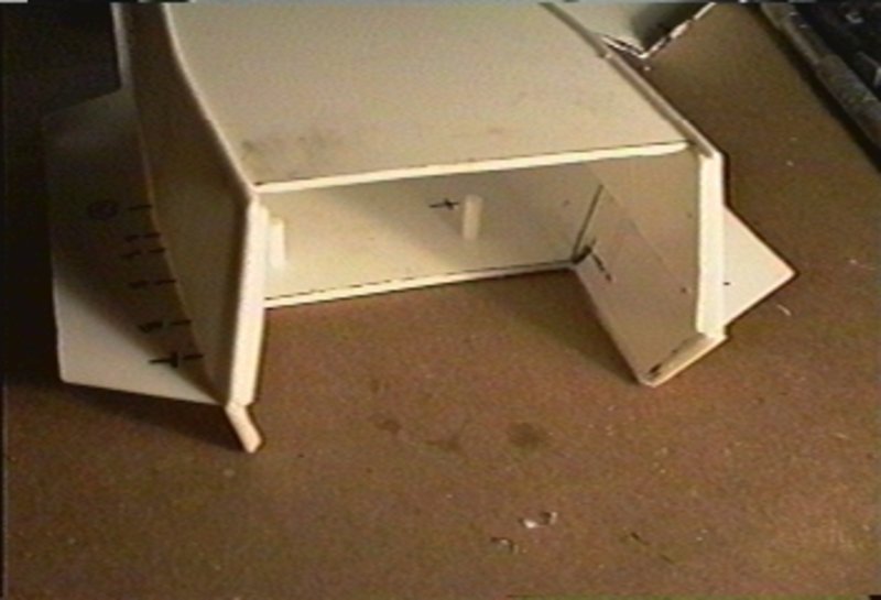
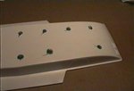
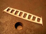
To build the correct engine shape, the floor will be cut 45mm from the
rear. This is the line marked in the photo. Heading to stern, there will be
a small 45° wall 5mm back and 5mm up. Then, a level floor for the next 8mm,
between the 40mm and 32mm mark. The next segment is supposed to go to a
point 21mm from the back and 32mm from the bottom. This leaves the
horizontal bottom edge of the impulse engine 12mm from the back.
An inaccuracy that will not be corrected is that the studio model and
full-scale mockup had straight walls along the sides. The model has angles,
making the floor a hexagon.
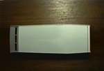
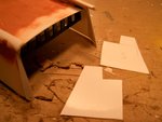
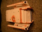
1999-07-31
The floor and rear wall pieces have been cut out.
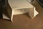
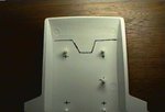
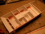
1999-07-31
This view shows how much of the model will have to be scratchbuilt.
Adding to the difficulty is that one segment of the rear stepped wall will
have to fit perfectly between the two halves.

2003
At this point, a break was taken. Other issues were discovered that were
very discouraging.
In 2003, an effort was made to restart the project. The roof, which is
supposed to slope down toward the rear, was cut along the length of the
model, lowered 4mm at the back, and reattached. This weakened the structure
of the model, and did not solve the inaccuracy that the roof, looking from
the rear of the shuttle, is supposed to be bowed up rather than flat.
Another feature was added: the curved rails at the top and bottom of the
hull's side walls. To do this, two telescoping polystyrene tubes were glued
one in the other for added thickness. It took several tries, but eventually
two straight-edged quarter-round pieces were cut from the tubing. These were
glued onto the top edge of of the side walls. However, these were very
flimsy as well.
Time for another break...
2005-05-16
Motivation strikes. The solution lies in the abandoning the interior of
the craft, instead adding reinforcing beams to keep the outside shape
accurate.
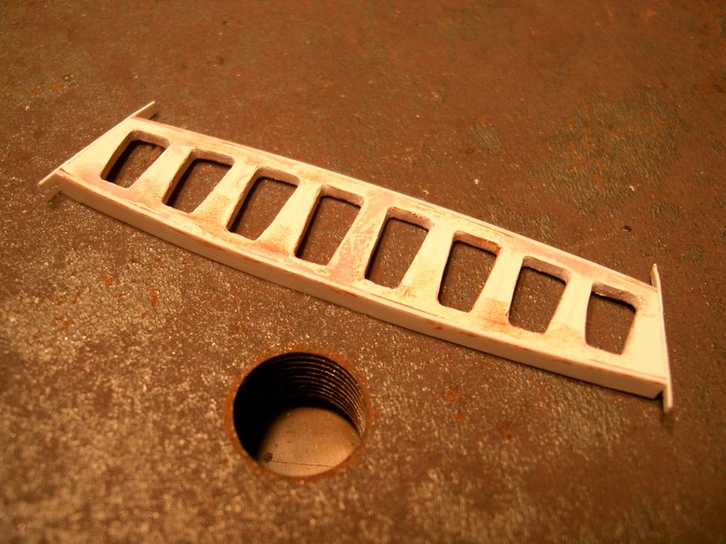
The other half of the solution was to start with an accurate impulse
engine. Using CorelDraw, an accurate part, complete with upper and lower
curves, was drafted and printed in full size. This was glue-sticked onto a
1/16" piece of polystyrene, and an accurate engine frame was cut.
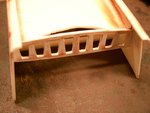
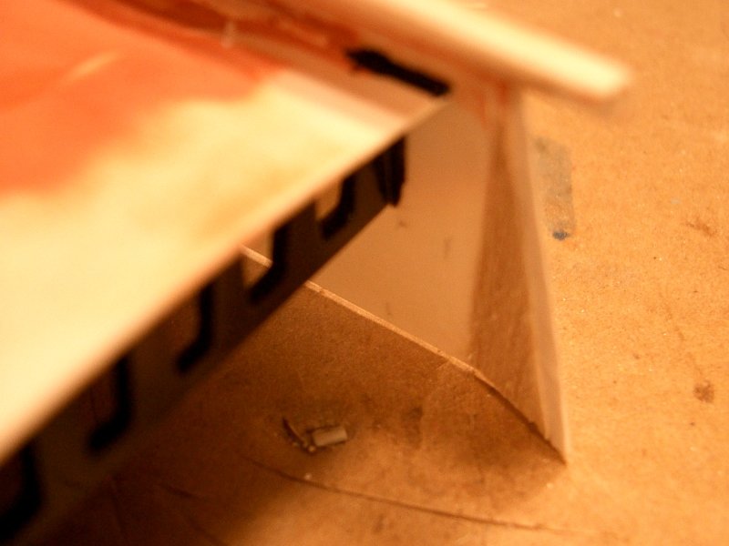
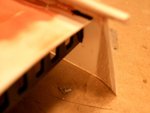
2005-05-16
The new engine frame was glued into place. A section of roof was cut
forward as not to block any of the engine holes.
2005-05-16
The roof needs to be curved, so sheets of 0.010" polystyrene build up to
the curve in the engine frame.
2005-05-16
As mentioned earlier, the interior was scrapped and replaced with
bracing. This was needed to account for the new shape resulting from the
modified roofline, and to prevent cracks in the rather large amounts of spot
putty.
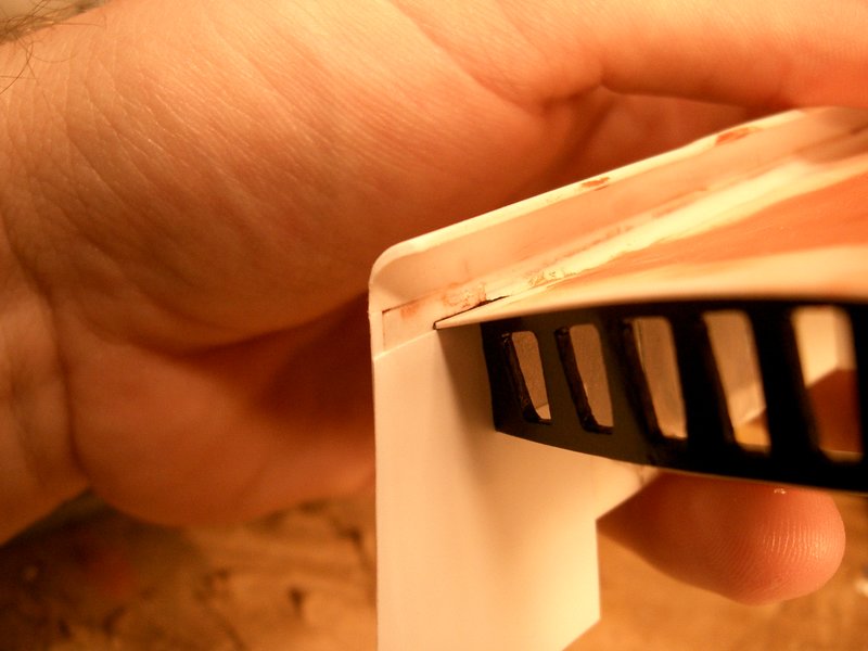
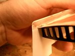
2005-05-18
Small pieces of styrene were added because the exterior walls of the
shuttle are to extend and angle inward at the rear. However, the inside wall
should be flat. To do this, two new interior walls were cut from flexible
0.010" sheet stock.
The curved top surface of the roof was puttied into smoothness. This took
several iterations.
Also, because the impulse engine will be lit, and there will be a piece
of frosted mylar behind the impulse engine frame, it will be very difficult
to paint later. The piece was primed and painted Semi-Gloss Black now. It
will have to be protected when the rest of the model is painted.
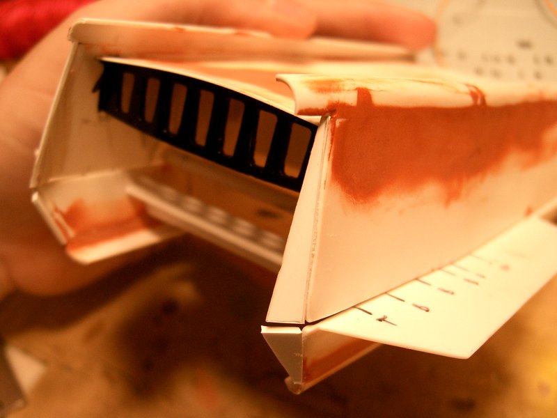
2005-05-18
Soft balsa wood is used to fill in the new angle at the rear end of the
model. The previously made wall covers will be glued along these.
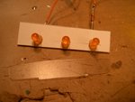
2005-05-18
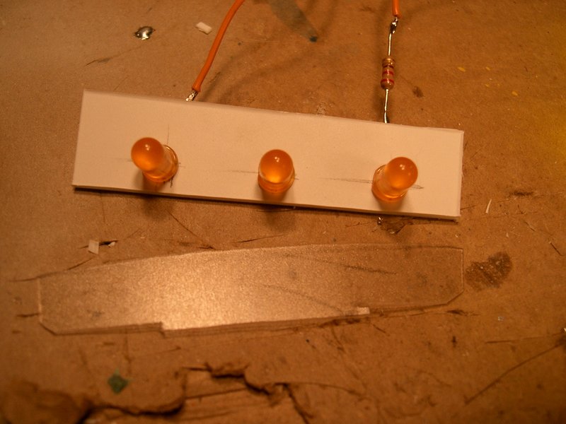
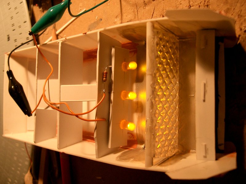
The impulse engine will be lit with three yellow LEDs. A piece of frosted
mylar was cut to shape to fit the engine housing.

2005-05-18
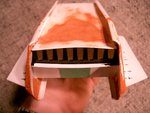
A test fit shows the current status of the shuttle. The curve rails at
the top and bottom of the walls were attached more firmly with straps of
thin polystyrene. Large amounts of putty cover all this. The first few steps
of the rear wall were built up in the lower half.
2005-05-18
The inside walls were glued into place along their rear and top edges.
They extend far enough down to reach all the way to the bottom of the lower
half of the hull. The curved rails were cut to their final length.

2005-05-18
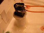
The LEDs lighting the impulse engine were further diffused with a piece
of the cover from a fluorescent light fixture.
2005-05-18
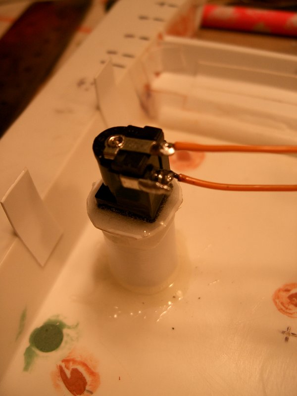
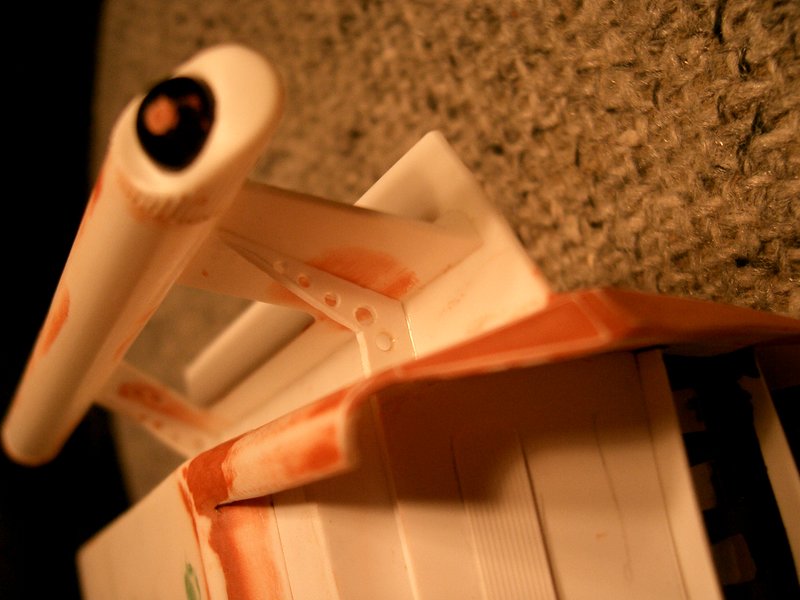
The model will be powered from an external power supply. To hide the
plug, it was placed at the end of a tube long enough to conceal a standard
12V DC power plug. The tube and plug were epoxied firmly to the lower half
of the hull.

2005-05-19
The two halves were glued together with epoxy and CA glue. The final
seams were hidden with spot putty, still unsanded at the moment.
2005-05-19
It was only after the two hull halves were glued together that the final
piece of rear wall was cut and put in place. A piece of masking tape holds
it in place as the glue dries.
2005-05-19
The warp engines were put in place. They were accurized by adding an
indented collar at the bow end of the units, and by embedding a bead in the
stern end.
Also seen here are the added plant-on details on the rear wall. These
were made from 0.020" and 0.010" sheet.

2005-05-19
The four steel brackets from the full-scale shuttle mock-up were
recreated with sheet styrene and glued into place.

2005-05-19
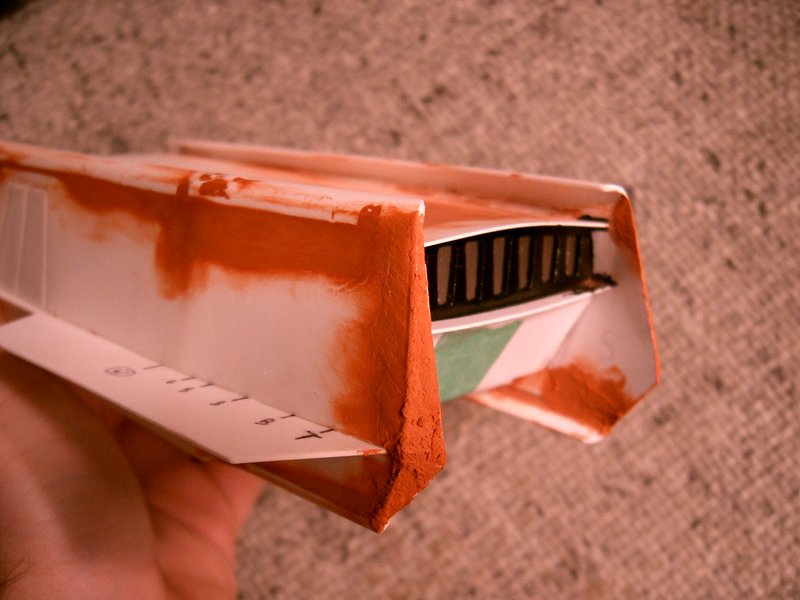
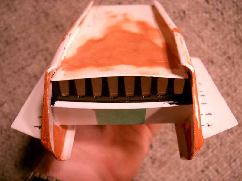
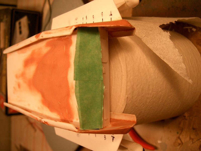
The model was prepared for priming. Since the impulse engine is already
painted, it is masked off.
2005-05-19
The model was primed with several thick coats of Krylon. The paint soaks
into the large amounts of putty and takes over a week to dry properly.

2005-05-29
The Galileo's paint scheme is fairly simple. The following Testor's Acryl
paints were used:
- Upper hull: Light Gray
- Lower hull: Dark Ghost Gray
- Warp engine caps: White
- Warp engine band and rear pieces: Silver
- Windows: Black
The model was then gloss sprayed with Future Floor Finish. After that was
dry, the kit decals were applied, and another layer of Future sealed them
in. The finishing layer was Testor's Dullcote. The windows were then shined
up with Future once more.
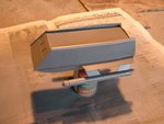
2005-05-30
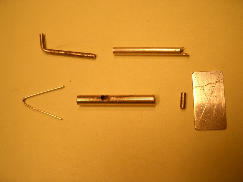
The only thing missing are the stand feet. The forward feet are created
from pieces of polystyrene tube and sheet. However, the rear foot needs to
be made of more rigid material. Various pieces of brass stock are cut to
resemble the foot on the full-scale shuttle set.
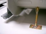
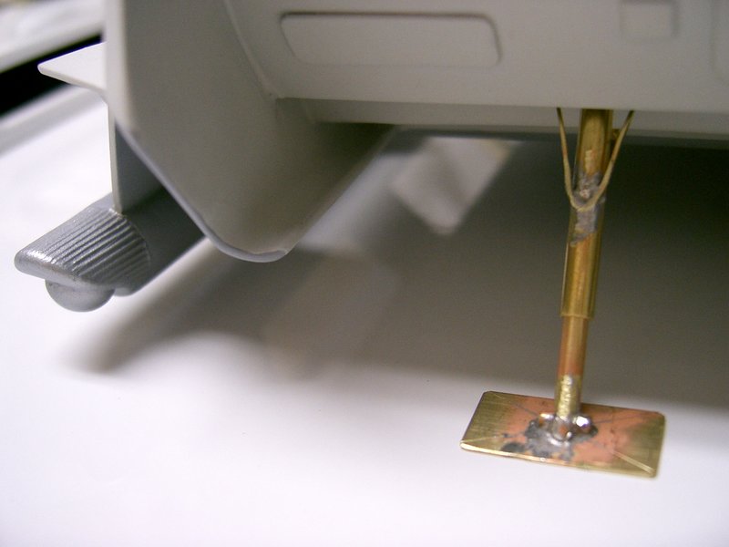
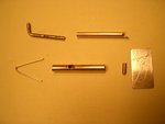
2005-05-30
The brass foot was soldered together, test-fit, and telescoped to the
correct length. Then it was cleaned up, primed, and painted silver.
Finally, it was attached more permanently to the shuttle.
2005-05-31
That is how the Galileo model was built. Far too much procrastination
went into this project. It took six years to build!
copyright ©2007-2026 pat suwalski