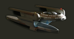
 I bought the Sci-Fi Spaceship Miniatures "Survey Class Vessel" model from a
fellow CultTVMan mailing list member back in the nineties. The model was
originally produced in the eighties, and is probably the best known Star
Trek vacuform garage kit.
I bought the Sci-Fi Spaceship Miniatures "Survey Class Vessel" model from a
fellow CultTVMan mailing list member back in the nineties. The model was
originally produced in the eighties, and is probably the best known Star
Trek vacuform garage kit.
I bought the Sci-Fi Spaceship Miniatures "Survey Class Vessel" model from a
fellow CultTVMan mailing list member back in the nineties. The model was
originally produced in the eighties, and is probably the best known Star
Trek vacuform garage kit.
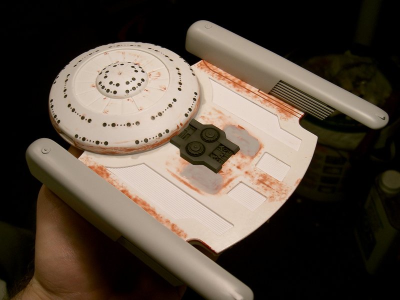
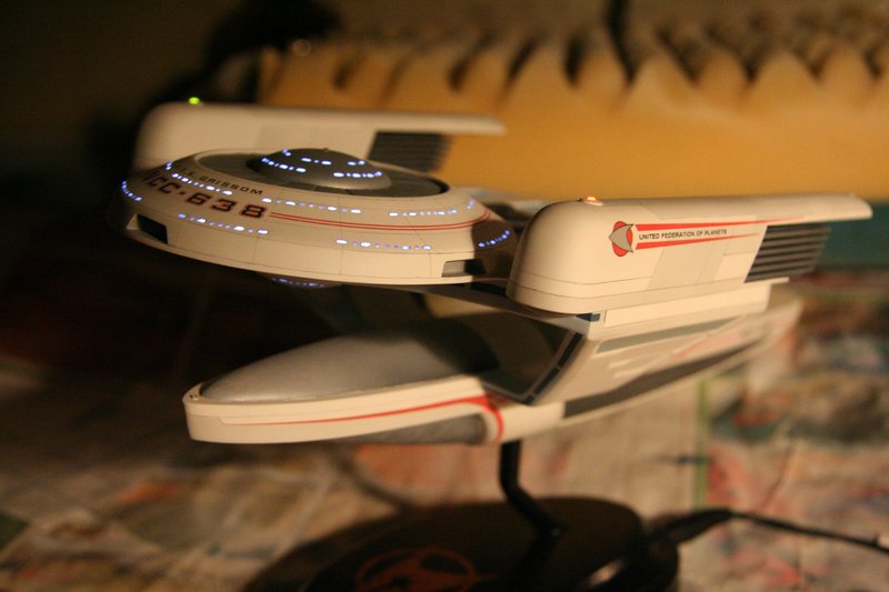
The build started as a diversion from my Enterprise-D, to test some techniques prior to using them on that model. However, as always, I got carried away with details.
In the end, this attention to detail was well worth it. The model turned out better than I could have imagined when I started.
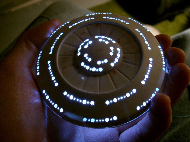
Photos of the completed build are showcased in the Models Area.
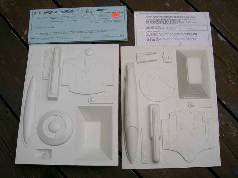
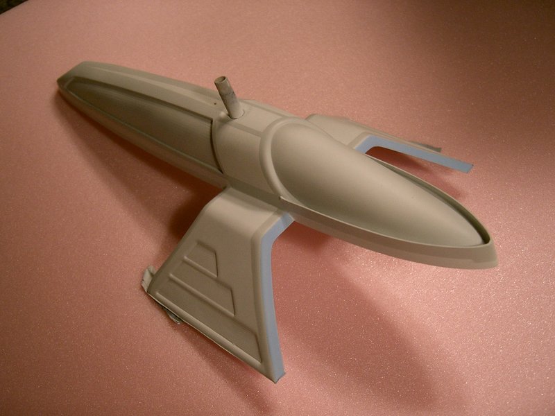
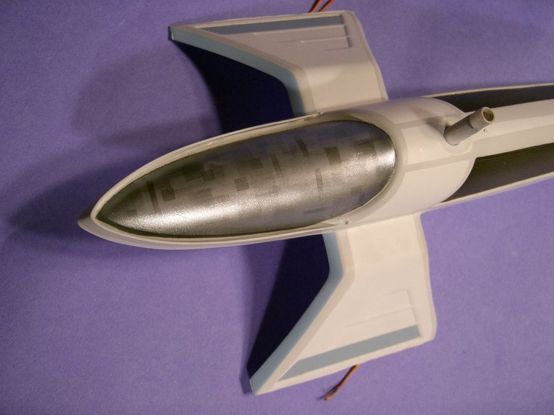
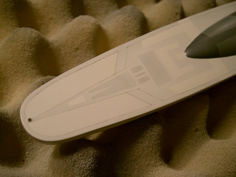
The Sci-Fi Spaceship Miniatures "Survey Class Starship" kit is a vacuum-formed kit. Unlike injection molded kits, vacuforms do not have perfect edges and alignment tabs to aid the builder. Since the parts are extruded from a single piece of sheet polystyrene, they can be very thin in places. The front tips of the warp engines, for example, were well under 0.5mm in thickness in this particular case.
The first step was to cut out the pieces with a sharp knife.
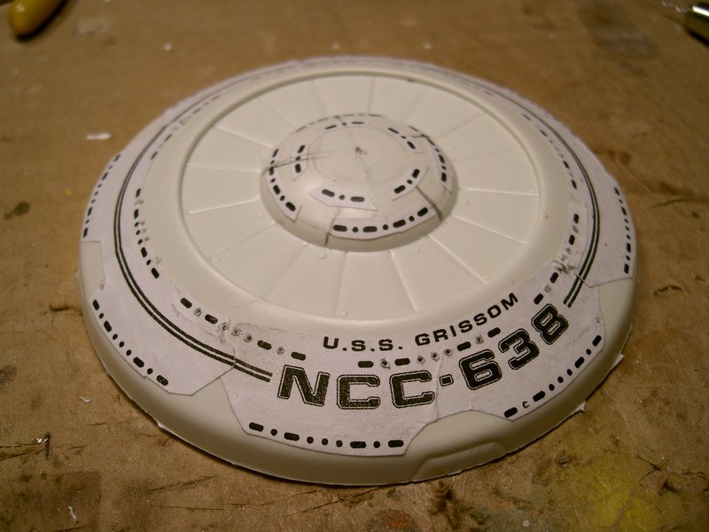
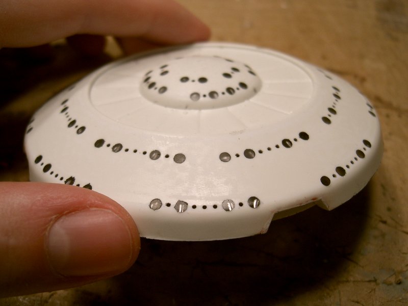
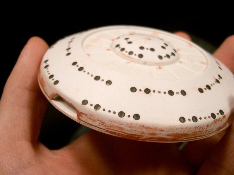
Since this model will be lit, it will need openings for the windows. Since no windows are marked, a photocopy of the PNT decal sheet glued on with gluestick serves as a reference. Good alignment is critical. The windows are drilled out with a #68 drill bit in a pin vise right through the paper.
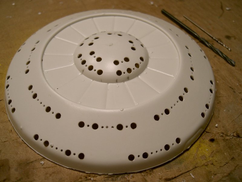
The result of the last step with the paper removed. The long windows would be painful to cut to their exact shape. To save a lot of time, a 3mm drillbit in the pin vise was used to expand the earlier holes on the long windows. Later, once the holes are filled and masked for painting, the extra area in the holes will not be an issue.
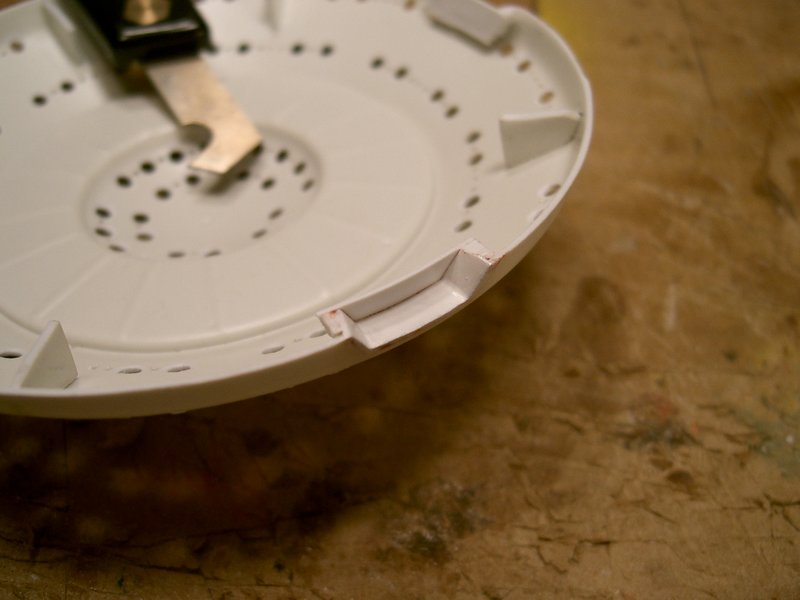
The shuttle or cargo bays around the perimeter of the saucer need to be made deeper. The walls are built up out of layers of 0.040" sheet, cut and sanded to their correct shape. A single strip of 0.020" sheet serves as the interior wall. They are pre-primed to check for flaws.
Some reinforcing frames were made from 0.040" sheet and placed around the perimeter of the saucer. These should provide more gluing surface and strength.
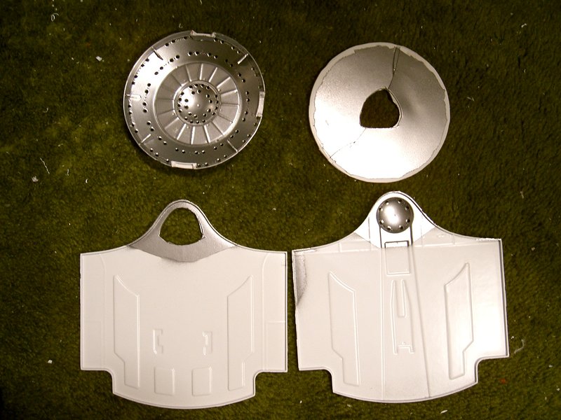
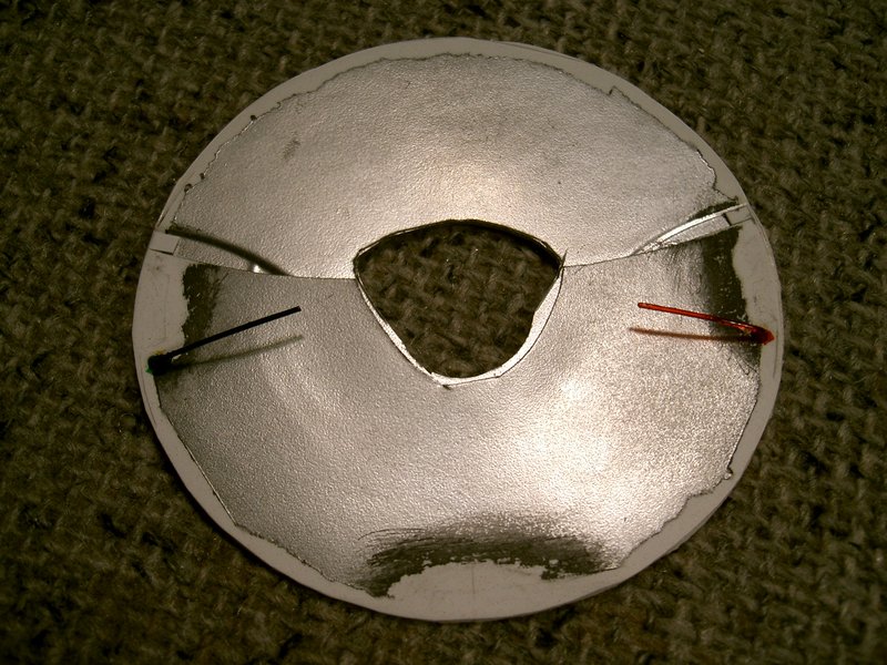
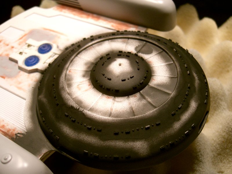
At this point, areas that will not be lit are masked off, spray painted with a layer of black paint, then spray painted with a layer of silver. The coat of black will prevent light leaks through the thin plastic, while the silver will provide good diffusion of light, reflecting it evenly inside the body.
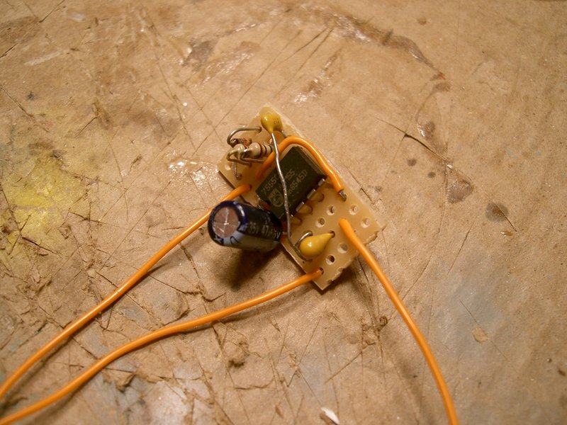
Many of the lights on the Oberth-class ship blink. Timing the reference material, the strobe speed is approximately 10 quick flashes every 8 seconds. A simple circuit is built around a 555 timer chip that provides this cycle. The board takes +12V and ground as input, and outputs a 12V pulse with the correct timing.
The large windows of the saucer were taped over with Scotch tape. The part was flipped over, and each window was filled with clear epoxy resin. I used a generic Bob Smith Industries epoxy, as it has a fairly good working time and dries clear. Bubbles were pushed out of the way with a toothpick. In areas that did not fill correctly, the tape was punctured to let the air escape, and the resin could then flow into the area.
The decision to cut the long windows round saved time in this step as well, since it was much easier to fill relatively large round holes with viscous fluid compared to slots of the correct final size.
The small round windows are left hollow for now. They will have fiber optic strands placed in them later.
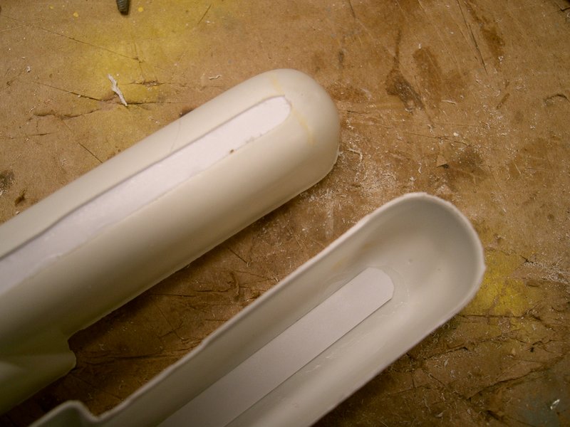
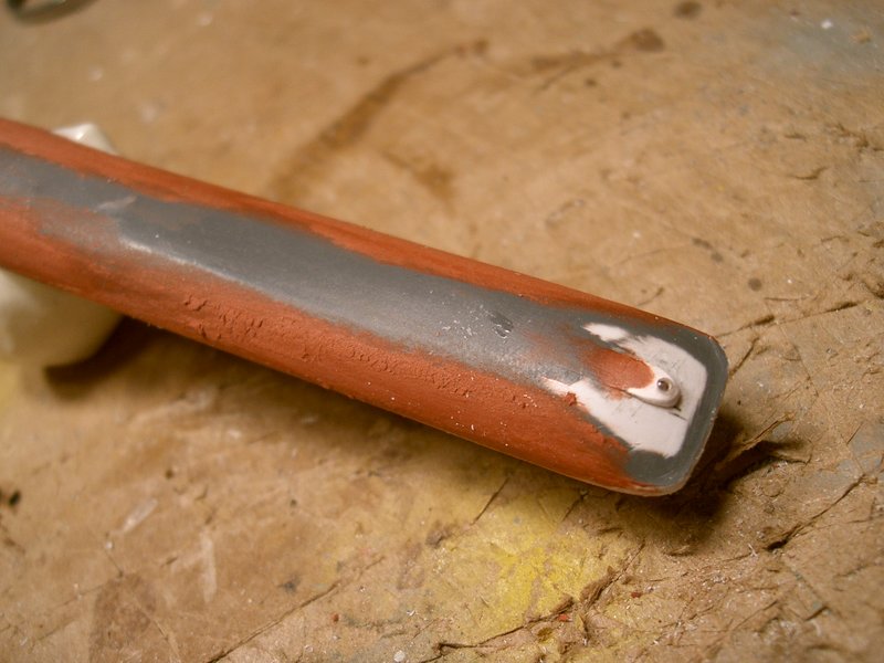
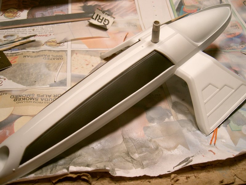
This kit has an inaccurate raised rib along the length of the warp engines. It was removed. A strip of polystyrene was glued to the inside in its place.
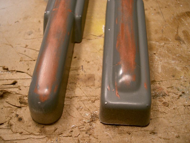
The breach from the last step was then filled with another strip of polystyrene matching the thickness of the kit plastic. The area was filled and sanded a few times. Krylon primer was used to point out imperfections in the work.
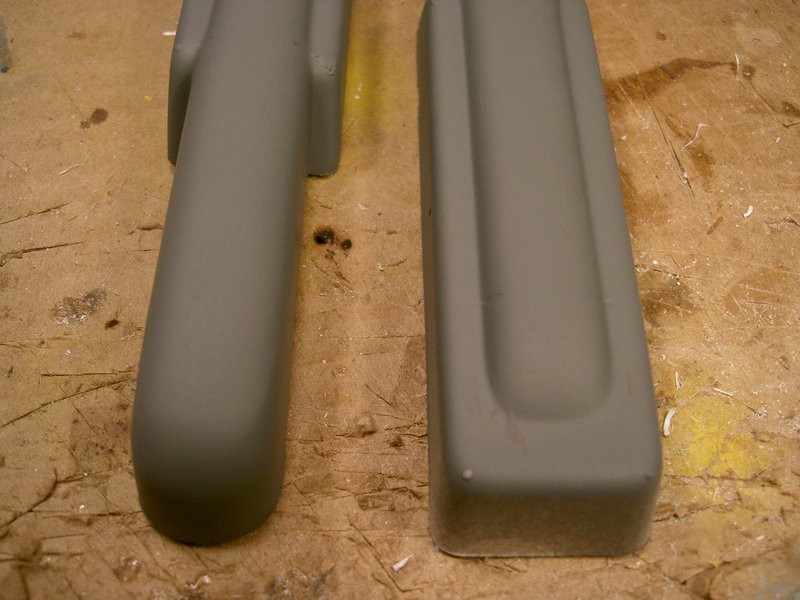
The warp engines are successfully corrected. The added strips of polystyrene inside the engines help to reinforce these very fragile parts.
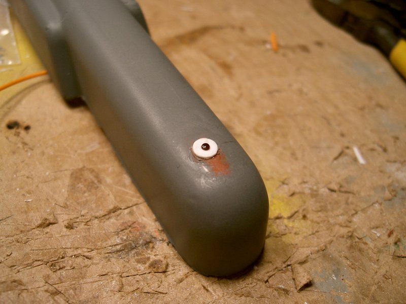
The front of the warp engines are supposed to have navigation lights that are slightly larger than the other lights on the model. Because of this, and because space is limited, LEDs are installed directly through the hull. The 3mm parts are brought down to the correct diameter by placing them in a drill chuck along a fine file and carefully turning them down.
Similarly, the rear end of the engines have flashing strobe lights. Because space here is very tight, a 0.030" fiber optic strand is run down the length of the engine, and its LED will be in forward half of the engine.
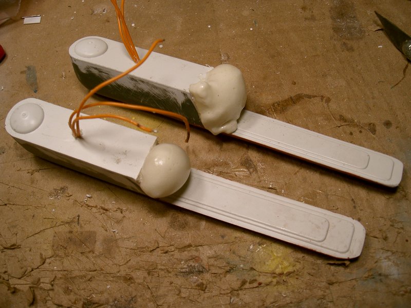
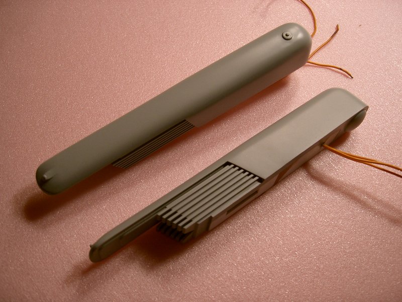
The engine pieces are glued together. All resistors are inside the engine, meaning the whole part runs directly from 12V. The three wires are for the front light, the rear strobe, and a common ground.
To increase the strength of the parts immensely, the front cavity is filled with expanding foam. The thinner area at the rear is filled with solid epoxy putty.

Another view of an assembled and reinforced engine.
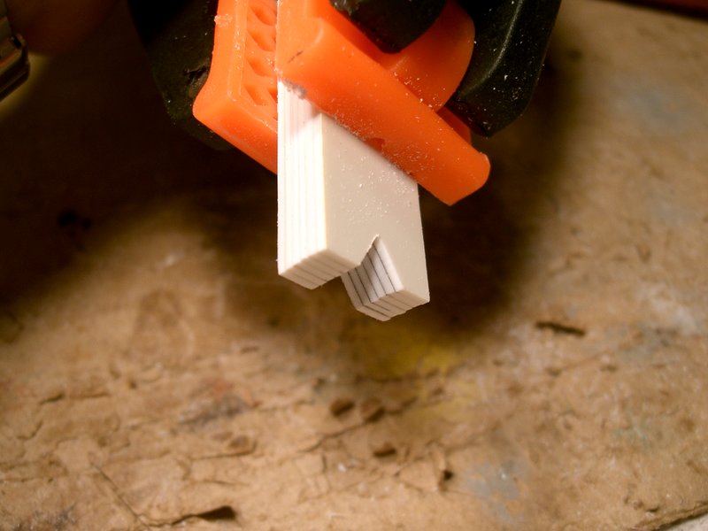
This kit does not come with the warp engine grilles. Instead, the builder is provided with a 0.040" sheet of polystyrene and a template for the layers of the part.
To get good results, the layers must lines up perfectly. There are six identical pieces required for each engine. To cut them to identical shape, the pieces for each engine are clamped together and filed to shape as a unit.
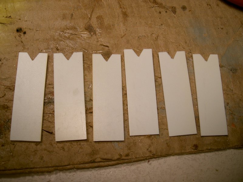
The result of the clamping-cutting-filing process is six identical blades. The process is repeated for the other engine, as well as for the smaller pieces that go between these slices.
Taking a break from the engines, the electronics from lower hull are assembled. First, a plug is installed. This will not only supply power, it will also be the mounting point for the stand, so it is reinforced with extra plastic strip and epoxied firmly in place.
Other components that go in here are a 12V voltage regulator, the strobing unit, and LEDs for the port and starboard formation lights within the lower hull. Since there are two lights on either side of the hull, 0.030" fiber optics are used. The LEDs are painted black so as not to leak light.
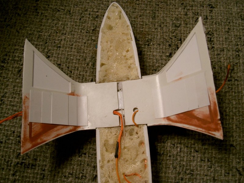
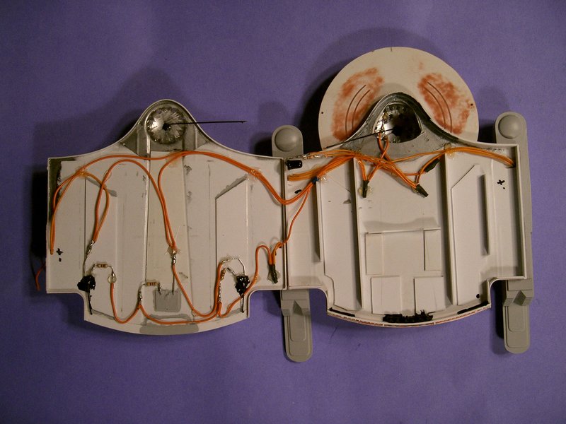
This is the final arrangement of the lower hull. In addition to the things mentioned for the last step, there is also a fiber optic strand for the lower strobe right next to the power plug. This will be attached to a LED later. The walls of the hull are reinforced with polystyrene strip, which will provide a larger gluing surface for the top cover.
There will be three wires run from the lower hull to the upper hull through the pylons: 12V, the 12V strobe, and a common ground.
The lower hull was filled with expanding foam. This will lock all of the wires in place, preventing things from coming loose over time. It also will add significant rigidity to the area around the plug which will support the weight of the entire model.
In hindsight, it would have been much smarter to fill the hull one thin bead at a time. As it stands, the center of the foam is still very wet. If a hole is made, wet foam-stuff comes shooting out. It will no doubt take weeks, if not months, to dry completely.
The excess foam is trimmed off.
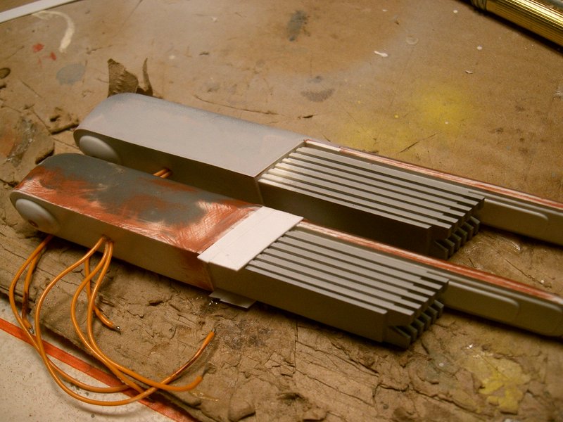
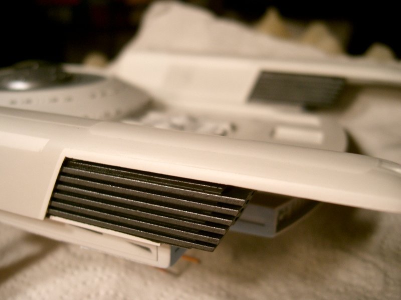
The warp engine grilles are assembled. The surfaces are sanded smooth and flush. The rear of the pieces is filed flat at the correct angle to fix the "staircase" pattern that had originally been formed. The same is done for the edges inside of the "v" cutout.

The rear curve of the engines were sanded to the correct shape. Then grilles were cemented to the engines. Perfect fit.
When it comes time to attach the top and bottom hulls, it will be very important that the alignment between the two is perfect. To help with this, stainless steel rods formed to the correct shape were glued into the pylons. The rods should ensure the shape does not change while the model is being built.
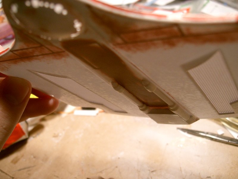
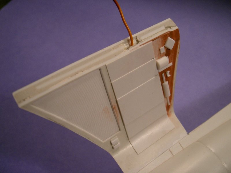
This kit's inner pylon pieces have cutout details formed backward. The original cutouts are filled in, and new ones are made. Their edges are beveled. The cutouts are backed with striped polystyrene. 0.010" sheet is used to make the stepped details.
The pylons are reinforced with sheet styrene. The goal here is for the inner pylon covers to be glued to something more concrete than just the thin edges. A channel was left for wiring.
The inner pylon parts are glued into place with epoxy putty and super glue. The three wires were run up through the trenches.
The tops of the pylons were sanded flat using a single large sheet of sandpaper on the floor.
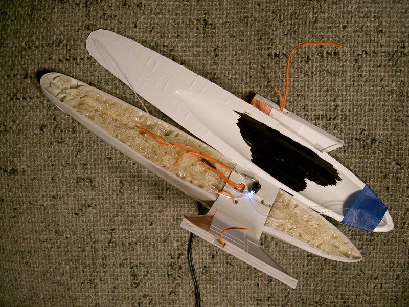
The final LED for the lower hull is put in place. It will light the three strobes in this part of the ship. There was already the fiber from the bottom of the hull, and two more were added coming in from the upper piece. Black paint was added to prevent light leaks through the bubble.

I want the sensor strips along the edge of the hull to be indented. Although the studio model simply had painted-on sensors, they would look much better if they were actually formed. To get the line straight, a strip of tape of the correct width was put on, and red paint was painted on to mark the line. The plastic was filed down to the line.

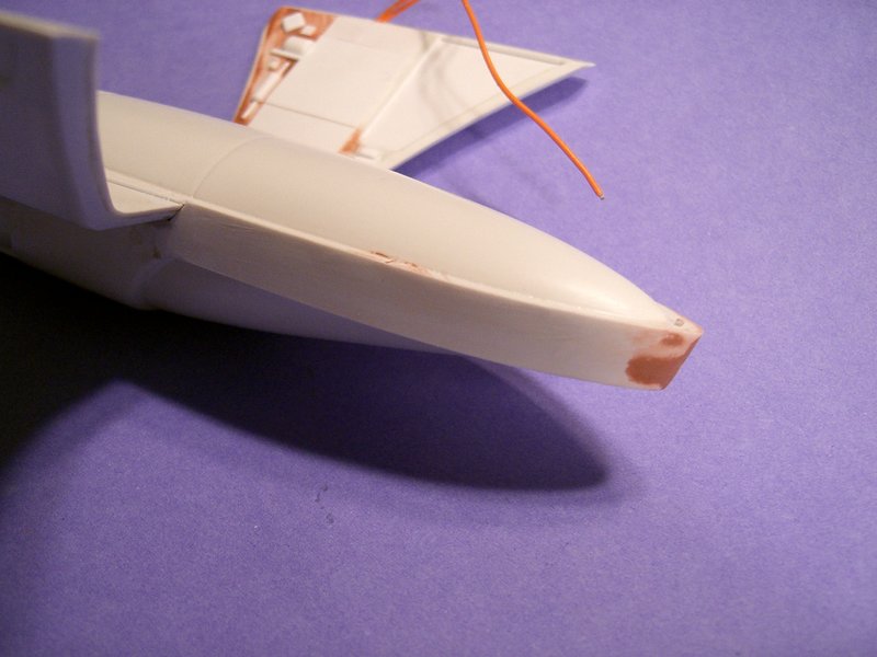
Seeing as the impulse engine part of the kit is completely incorrect, a part will have to be scratchbuilt in its place. Recent catalog photos from the Christie's auction and DVD reference show the correct shape. A sketch of the correct engine shape will serve as the basis for a better part. The beveled details on the kit will need to be removed to make this work.
Also, the striped panels were cut out. They will be replaced with better-looking striped sheet.
The details on the hull piece were all removed, backed, filled, and sanded. Striped sheet stock was put into the cutouts from the previous step. The new impulse engine is designed from various diameters of tubing.

The impulse engine was designed with a piece of frosted mylar to diffuse the light from two 3mm red LEDs. The areas outside the center rectangle of the impulse engine will be painted black. A test fit looks good.

A final look at the new impulse engine. The main part of the engine housing is actually still largely the original piece.

A part of the kit that lacks a lot of detail is the impulse crystal "backpack" that sits directly behind the saucer. Seeing as this is a very visible area, a more detailed part is needed. Part of the problem is solved with DLM's replacement impulse crystals. Careful observation of now-available reference materials allowed for a decently detailed recreation of the whole part.
Much as with the bottom piece of the upper hull, details on the top half were removed, and the cutouts were replaced.

To space the two halves of the upper hull properly, 1/4" strip stock is glued into place.
The final part that requires extra scratchbuilt detail is the area at the very rear of the upper hull. It was recreated as closely as possible with polystyrene stock, a few resin greeblies, and six 3mm LEDs. The LEDs will not be lit, but their shape is precisely what is needed.
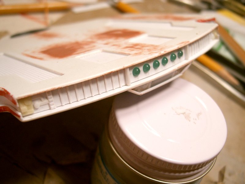
Lighting the smaller saucer windows will be accomplished with 0.030" optical fiber. Each strand was cut to a length of about 10mm. The strands were glued in so that they stick out just over 0.5mm on the outside. This will allow for easier painting. The fibers will be painted over and then sanded down flush with the hull. Because there will be extra pressure on the fibers during sanding, they were glued down more securely than usual. First, they were attached with small drops of CA glue, then epoxy was used to really hold them in.
At this point, it became clear that the way the kit is designed, the nacelle grilles were too long. To compensate, 10mm of extra nacelle wall were added with strip styrene.
After sanding and priming, the warp engines look great. The extra wall has the added benefit that the grilles actually do go into the nacelle.
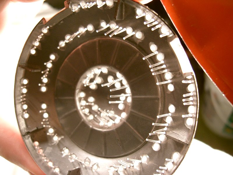
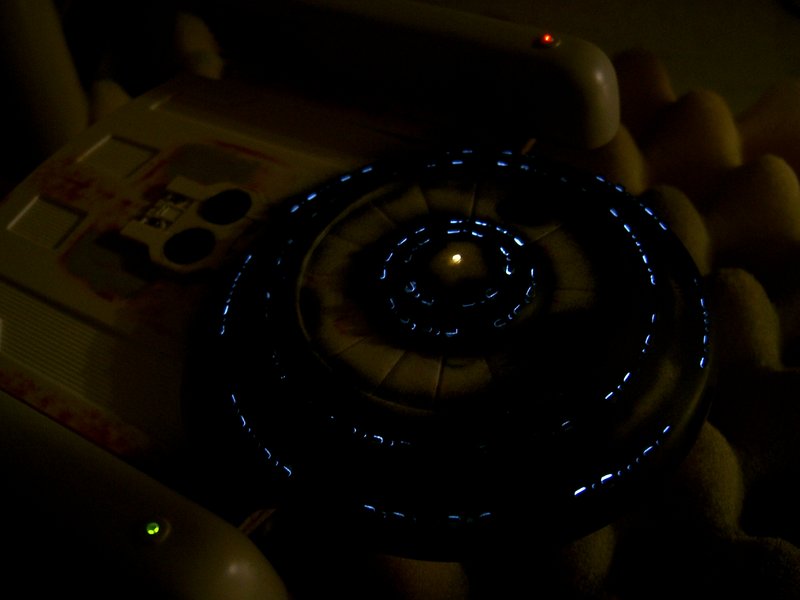
An initial light test with three white LEDs shows that they produce the perfect quantity of light for the saucer.
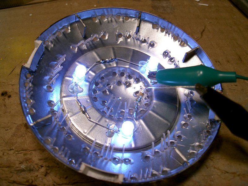
The three LEDs are wired in a single series. This is efficient, as it requires a small resistor to operate at 12V, and should produce little heat. The LEDs are physically glued to the top of the saucer and pointing down. The round part of their lenses has been filed down for a less focused beam.
The bottom of the saucer is supposed to have navigation lights. The saucer is too crowded for any additional LEDs, so optical fibers painted clear red and green, catching light from the saucer's window illumination LEDs, will have to suffice. They will not light as brightly as dedicated LEDs, but they should be visible.

A light test of the bottom of the saucer shows that the lighting situation is acceptable here. The windows in the lower dome are actually catching light from the LEDs in the top part of the saucer.
With all tests satisfactory, the saucer halves are glued together. The internal ribs of the saucer each received a small ball of epoxy putty, while the rim was glued with liquid epoxy and CA glue. The seam has been cleaned up.
Finally, all of the major components of the upper hull are glued in place. The "backpack" is just sitting there for test fit.
Both halves of the upper hull are now wired up. Two extra 3mm LEDs were added for the formation lights in the bottom half at the rear, and the impulse engine LEDs were also hooked up.
What makes this tricky is that there is an extra strobe LED for the lights at the very top and bottom of the saucer. It is actually in the corner of the top half of the hull, with fibers painted black directing the light to the correct location. The tips of the fibers are painted Tamiya Clear Orange to replicate the incandescent bulb colour of the strobes on the studio model. While the halves of the hull are being glued together, the two fibers will have to somehow be inserted into this LED.
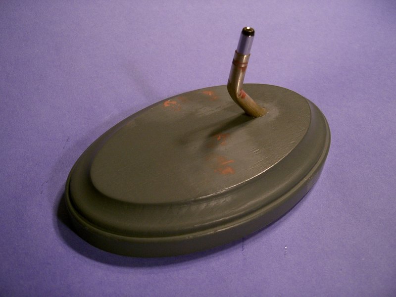
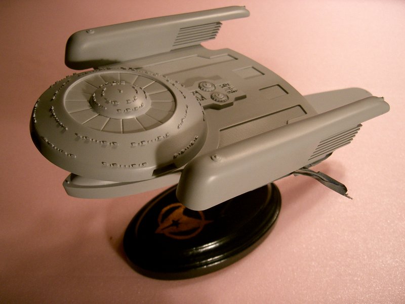
It seems like a good time to create the stand. The base is a beveled pine plaque from Michael's arts and crafts store. brass tube was bent because I wanted the model to sit pointing a few degrees upwards. The plug was wired up and epoxied into the tube. Because it was a little long, a thin brass collar was added. The wooden base itself has a small trench where the wires from the tube travel to a plug on the far end.
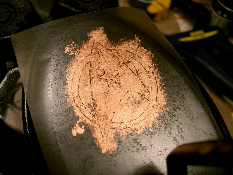
After the base was primed and painted with Krylon spray paint, a era-appropriate Starfleet logo was added. The emblem stencil was cut from frisket film. Testor's Copper enamel paint was dabbed on with a piece of toilet paper to create a rustic effect.
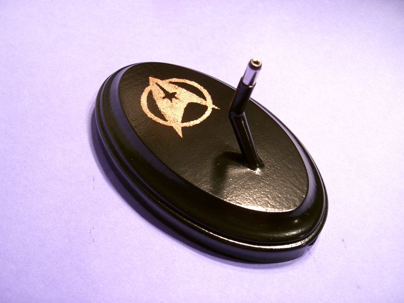
The completed stand looks great. The lower hull sits very nicely on it.
Now that the two halves of the upper hull were glued together, the trench for the sensors looked far too deep and wide. To fix this, strips of scale channel were glued into the trench. Small strips were added to split the sensor palettes. When everything was puttied and sanded down, they look just right.
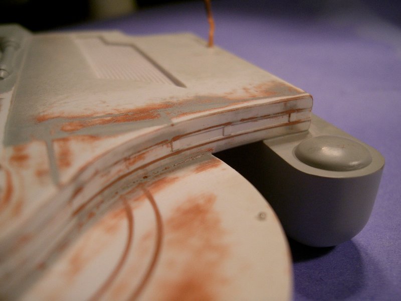
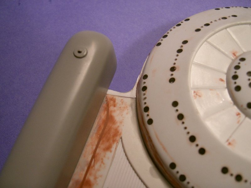
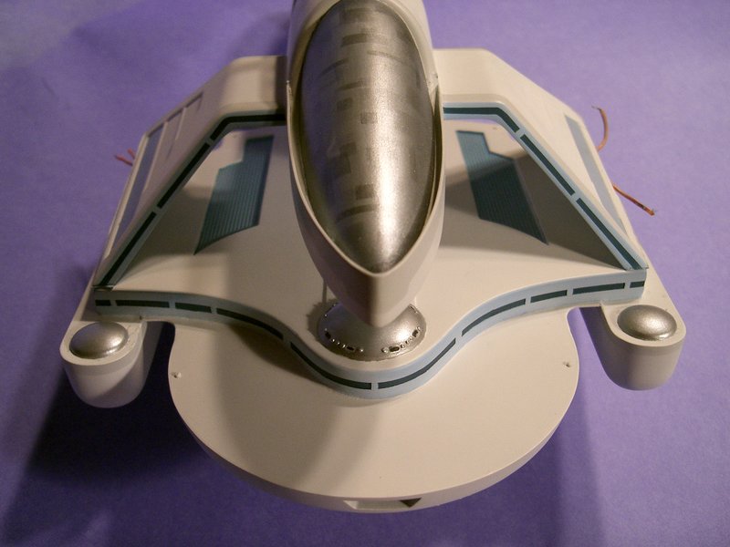
Back to the lower hull. A small omission around the sensor bubble (besides its shape) is that on the studio model, the bubble was skirted with hull. This also made the hull look much taller than what was vacuformed on the kit. To fix this, a 0.5" wide "V" strip was cut from 0.010" sheet styrene and glued into place. Another (narrower) 0.010" strip was then glued inside of that for added thickness. To reinforce the bond, the model was flipped upside-down, and a quantity of epoxy was poured into the void between the bubble and the skirt.
Also at this point, some detail greeblies were added to the inside of the pylons. These were very difficult to see in the movies, but they were definitely there.
An extra touch of accuracy to the upper hull involved adding small "L"-shaped pieces between the warp engines and the saucer. This was cut from 0.020" sheet stock.

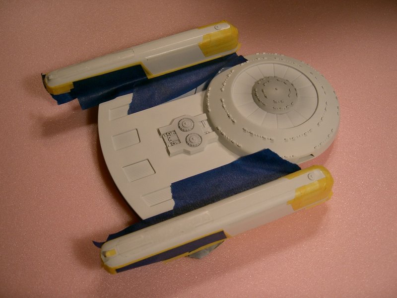
The lower hull is prepared for priming. The tops of the pylons are masked because they will need a clean surface to glue to the upper hull. The shape of the ship requires that both halves of the ship be painted separately and then glued together.
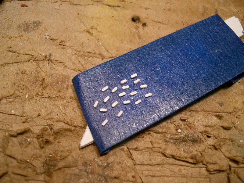
Before the upper hull can be primed, the long windows still need to be masked. Rather than cutting rectangular pieces of masking tape, windows with a proper pill shape were made from polystyrene. A 3mm-by-1mm strip had its corners rounded with sand paper. Then, a sharp knife was used to cut 1mm-or-so lengths. These pieces were laid out on a piece of masking tape. Microscale's Micro Liquitape was applied to each mask. This product remains tacky after it dries, much like the glue on adhesive tape.
Using tweezers, the tiny masks were stuck onto the windows of the lower saucer dome. They stuck with more force than expected, which should ensure a good seal.
The procedure was repeated for the upper saucer. The other advantage of these plastic masks over tape is that it should be easy to pluck them off with tweezers after painting.
Flat Black paint was airbrushed at this point to lightproof all but the masked areas of the windows. The paint did not apply very smoothly, and will require some clean-up later.
Checking for light leaks at this point proved very important. Because the masks have a millimeter or two of height, it is easy to miss a spot where paint flow is shadowed by the mask. A second coat of black was applied to fix these areas.
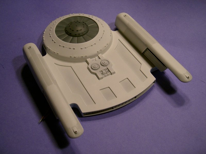
Finally, the two hull sections are primed. They are not glued together yet. The primer used was Tamiya Fine Gray Primer. It manages to be very thin, not removing details, while still drying quickly and with a smooth finish.
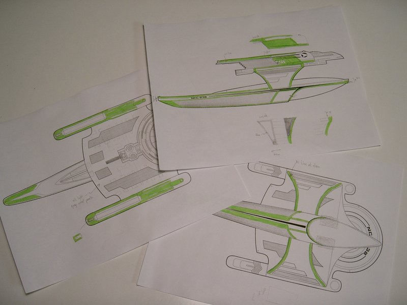
The paint scheme on this ship is surprisingly complex. The base colour is white, but many of the features are painted with a 50-50 mix of Gloss White and Light Gray. The gray areas are marked with green on the diagram. All paints on this model will be Testor's Acryl.
The lower hull is painted. Much frisket and masking tape went in to make this possible. The blue stripe is Flat White with a few drops of French Blue.
The upper hull is masked for similar treatment. Here, the paint scheme is even more complex, with 1mm-wide pinstriped masks. Since there are no panel lines to follow on the kit plastic, all masks had to be measured and cut very carefully.
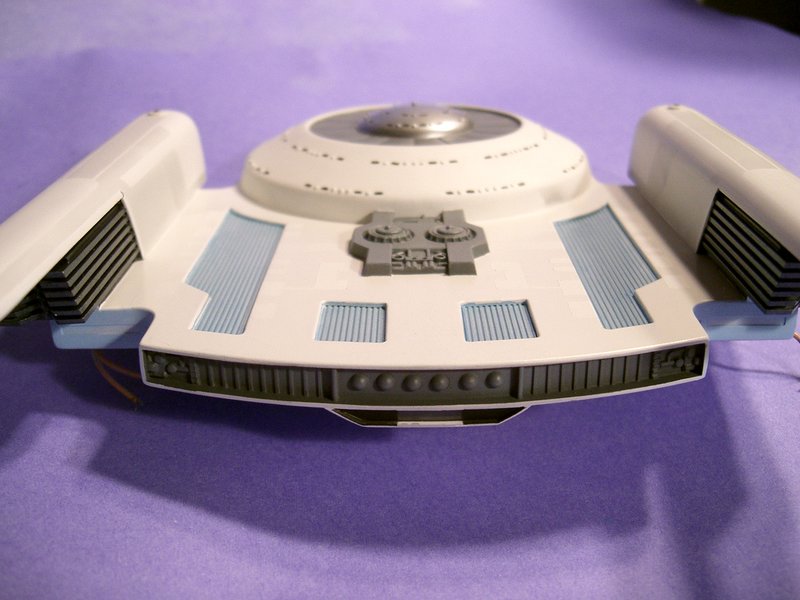
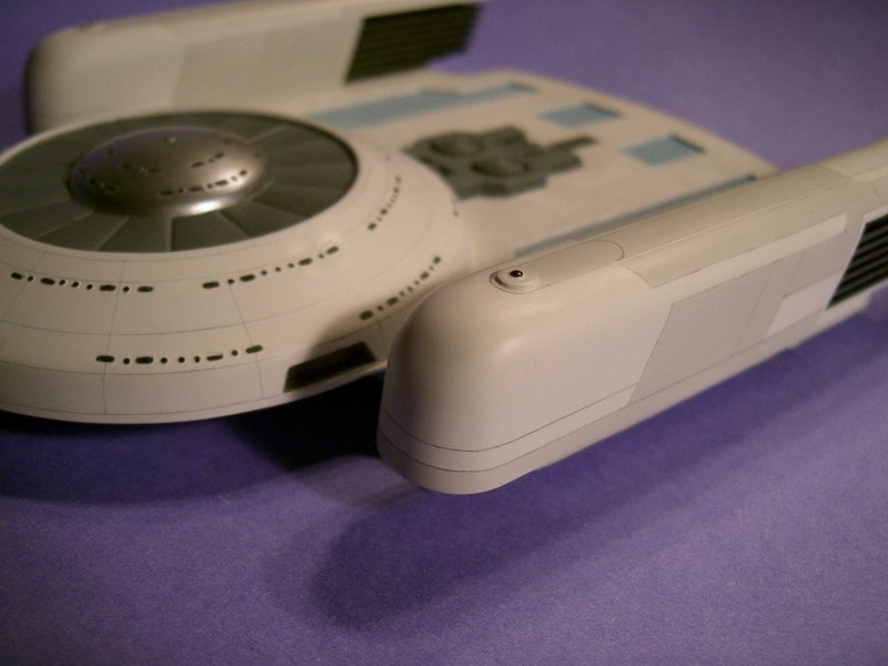
The gray paint scheme of the nacelles is complete, as is the area around the bridge. The base colour here is Gunship Gray. The edges of each segment were highlighted with Dark Ghost Gray. The whole thing was toned down with a thin overspray of Euro1 Gray mixed with Dark Ghost Gray.
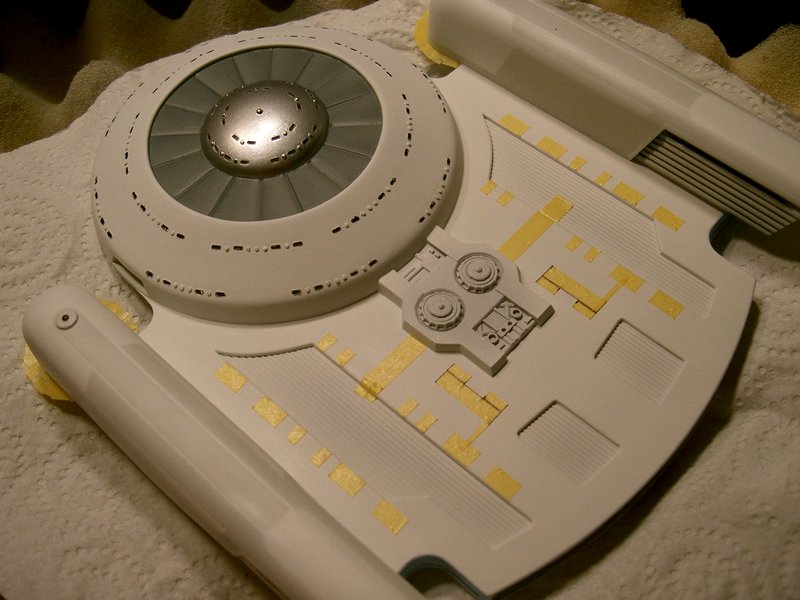
The bridge was painted silver, as was the dome on the underside of the saucer, and the domes under the warp engines. The pattern on the top of the hull was masked out.
At this point, it was safe to remove the long window masks before the Liquitape became stale and brittle. The windows turned out sharp, with only minor touch-ups needed.
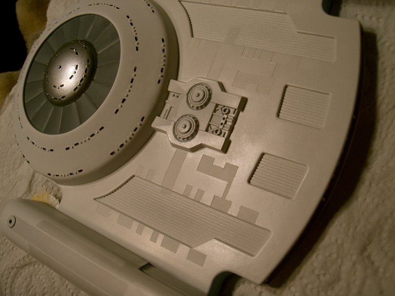
The paint used for the pattern was Gloss White with a few drops of Light Gray. The pattern is meant to be very subtle. Much of the effect is created just with the added thickness of paint at each panel's edge.
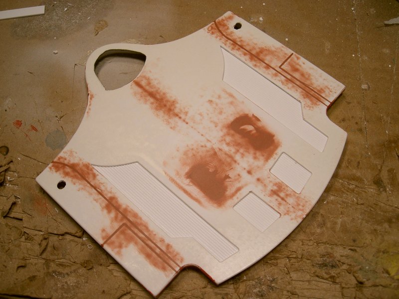
The cutouts in the lower hull were first pre-shaded with black toward the outer edges. The main paint colour was a mix of Leather and Dark Ghost Gray, for a brownish shade. Once that was applied, more Black and Dark Ghost Gray were used to add highlights and shadows.
The warp engine grilles were painted solid Gunmetal. Once that dried, the visible surfaces were drybrushed with a mixture of Gunmetal and Silver.
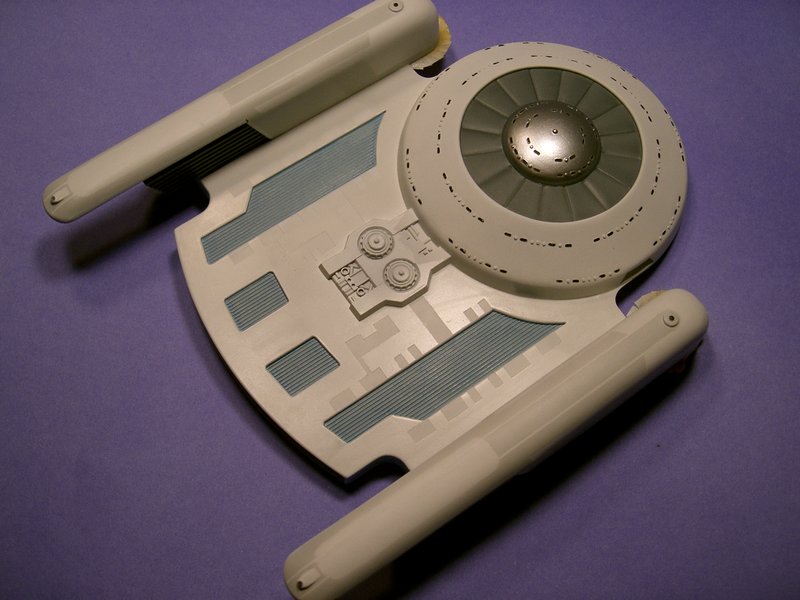
Paint for the blue-gray cutouts in the main upper hull was mixed from White and equal (small) amounts of French Blue and Zinc Chromate. After the base colour dried, the grooves were washed with a deeper blue colour, a very thin French Blue.
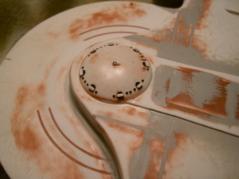
The sensor bubble was fairly tricky to paint. Painting started with a solid Gunship Gray, pre-shaded with a layer of black at the edges. The main colour is Silver, dulled with Dark Ghost Gray and Gunship Gray. The middle was highlighted with pure Silver. Frisket film with several small rectangles was then used as a mask to create the pattern, using thinned black and white paint. The key was to not paint solid squares, but just get a hint of either shade. Some dimension was added with a final thinned-down overspray of Silver.
The cutouts on the sides of the pylons were painted with the same paint as the cutouts on the upper hull.
Both the "backpack" and the rear wall of the upper hull were painted with a base colour of Gunship Gray. Highlights were drybrushed with Dark Ghost Gray. Also, the black areas on the impulse engine were so painted.
Paint for the sensor strips was mixed from various shades of gray, tinted with French Blue, which produced a nice, toned-down Navy.
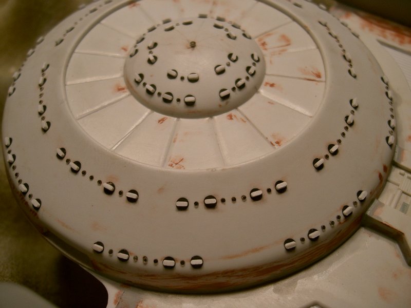
The upper bubble on the lower hull was painted much like the sensor bubble. The edges were started off pre-shaded with black. A mixture of Dark Ghost Gray and Silver formed the main colour, which was then highlighted with a clean Silver. The panels at the rear end of the bubble were painted with a highly thinned Gloss White.
The greebly areas at the rear of the pylons were painted in the same scheme as the darker details on the upper hull.
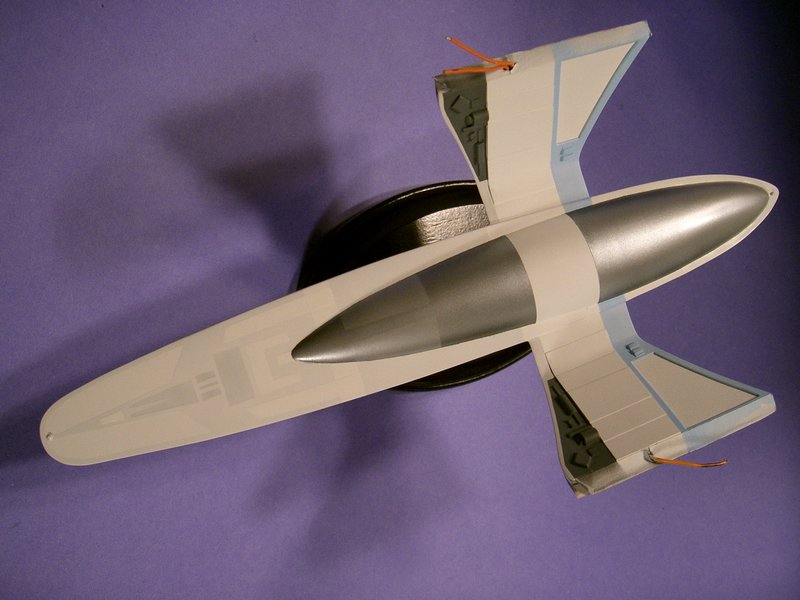
The pattern on the tail was more complicated. Since no good reference photos exist of this area, there was a lot of guesswork involved. A pattern that should be close to the real thing was made with Light Gray tinted with various amounts of Gloss White. Thinned Gloss White was then used to carefully tone down the panel line edges.
Panel lines throughout the ship were drawn by hand. A 2mm Staedtler drafting pencil with frequently-sharpened 4H graphite worked nicely. The nice thing about using pencil is that mistakes could easily be corrected with a good-quality eraser.
Once all the panel lines were drawn on, the lower hull was glossed with Future Floor Finish. A few days of drying, then the decals were good to go on. Another couple of days were left to allow the decals to dry thoroughly, and they were then sealed in with a final coat of Future.
Panel lines on the upper hull were more tricky. A Staedler compass was used to draw the concentric panel lines on the saucer. Various flexible rulers and masking tape served as guides for the lines here. It was tricky, and being able to erase was certainly taken advantage of. The harder-to-reach areas took several tries.
Just before the panel lines were drawn on, the fiber-optic windows were sanded down to remove the paint that was covering them. To protect the model, all sanding was actually done through frisket film. The bumps of the windows sanded through the film, while the hull was untouched. The thinness of the film also guaranteed that the fibers were sanded very closely to the hull; nearly flush.
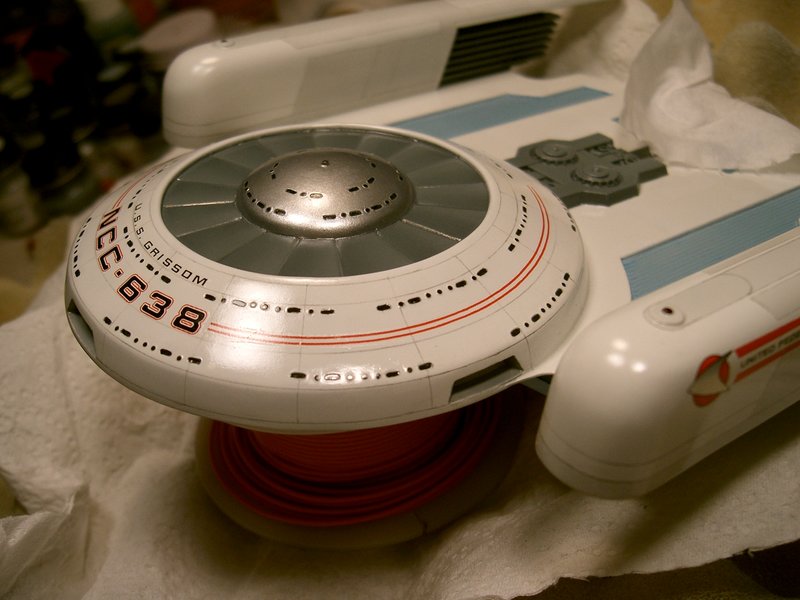
As with the lower hull, once the panel lines were drawn, a coat of Future was applied, followed by decals, and another coat of Future. The decals used were from JTGraphics. They fit perfectly, which is surprising when all of the modifications to the model are considered.

The two halves of the model were finished with Testor's Acryl Dullcote.
Unfortunately, while the alignment after joining the two halves was great, a larger-than-expected gap remained. There was no way to test for this earlier, since the wires had been in the way. The workaround is time-consuming puttying and painting. Much like auto body work, everything has to match perfectly.
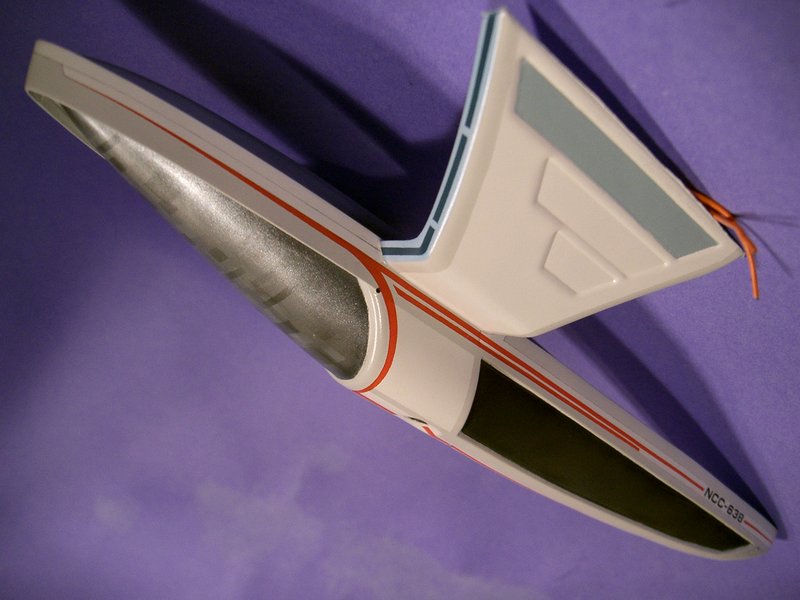
After all is said and done, the seam turned out well hidden. The model is effectively completed.
A small amount of black chalk powder was used around the impulse "backpack" and in the cut-outs for added depth. Applying it after the dullcote makes the powder adhere better. A very fine mist of dullcote was sprayed afterwards to keep the powder down.

This model took nearly sixteen months of work. While the building started off somewhat slowly, ideas for good ways to do things were always being planned. The work eventually picked up. The result is a model I am proud of.
copyright ©2007-2026 pat suwalski